Inter-stage air feeding structure of centrifugal compressor and design method thereof

A technology of centrifugal compressor and air filling structure, which is applied in mechanical equipment, computing, machine/engine, etc., and can solve the problems of increasing, rotating and stalling airflow, affecting the reliability and economy of the device, etc.

Active Publication Date: 2015-04-22
SHENYANG BLOWER WORKS GRP INSTALLATION MAINTENANCE FITTINGS
View PDF6 Cites 23 Cited by
  • Summary
  • Abstract
  • Description
  • Claims
  • Application Information

AI Technical Summary

Problems solved by technology

If the gas filling structure is not designed properly, it may cause a large distortion in the flow field of the mixed gas outlet
Since the current development of the basic stage is based on the design of uniform flow conditions, the inhomogeneity of the inlet flow field of the next stage directly causes the inlet angle of the blade to change in a wide range, which will not only affect the efficiency of the stage, but also cause rotation in severe cases. Severe air pulsation phenomena such as stalling will make the unit unable to work normally, directly affecting the reliability and economy of the device
Due to the complexity of the gas filling structure and the increasing number of such products, it is time-consuming and labor-intensive to use the CFD method to design each time

Method used


Image

  • Inter-stage air feeding structure of centrifugal compressor and design method thereof
  • Inter-stage air feeding structure of centrifugal compressor and design method thereof
  • Inter-stage air feeding structure of centrifugal compressor and design method thereof

Examples


Embodiment Construction

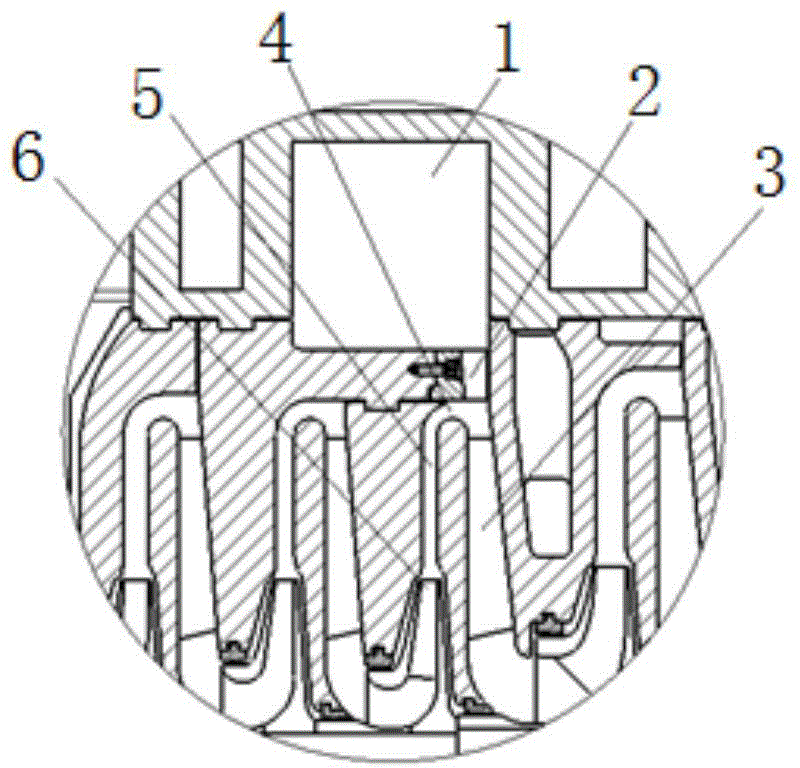
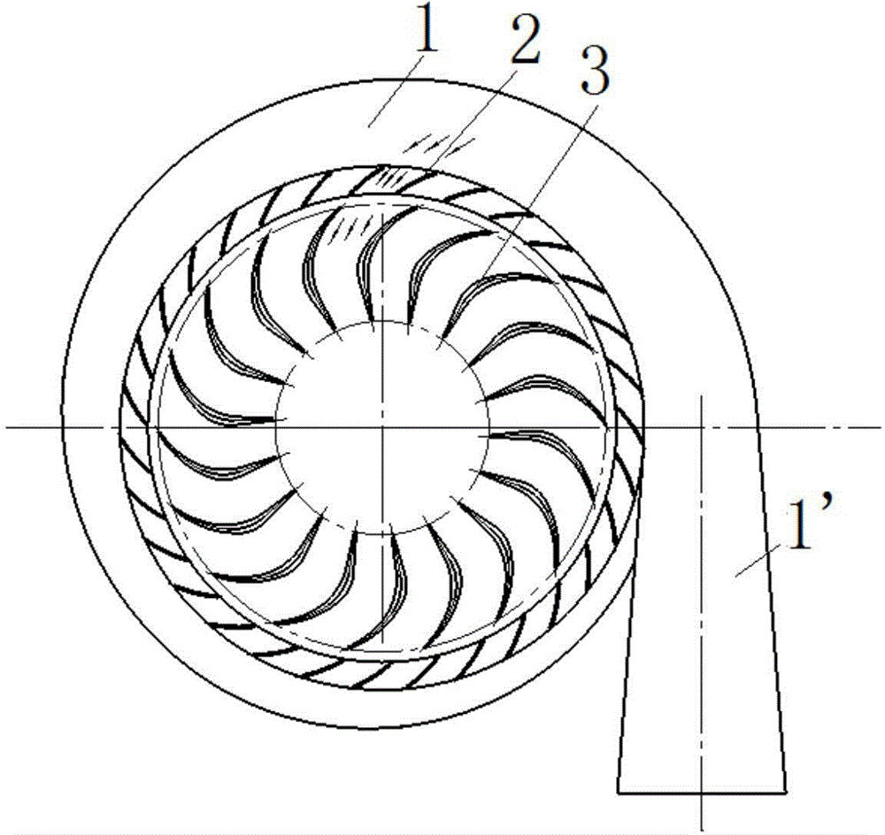
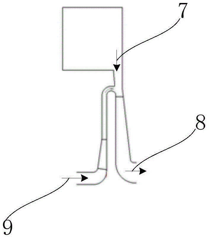
[0052] see Figure 1-3 As shown, the centrifugal compressor interstage air filling structure provided by the embodiment of the present invention is applied to the centrifugal compressor. Specifically, an air filling port is provided at the bend 4 of at least one stage of the centrifugal compressor, and an air filling structure is added to the air filling port, so that the main air flow 9 is introduced into the air filling airflow 7 . The aeration structure includes an aeration volute 1 and an aeration volute 2 . Wherein, the volute of the air-filled volute is a variable-section volute. The aeration guide vanes 2 are evenly distributed in the same shape along the circumference behind the volute of the aeration volute 1, so as to improve the circumferential uniformity of the air flow and change the air flow angle of the aeration, so as to ensure that the aeration air flow 7 is consistent with the main air flow 9. No large angle of attack will be produced when flowing into the ...


PUM


Abstract

The invention provides an inter-stage air feeding structure of a centrifugal compressor. An air feeding port is formed in the bend of at least one stage of the centrifugal compressor, and the air feeding structure is additionally arranged at the air feeding port, so that fed airflow is led in for main airflow. The air feeding structure comprises an air feeding volute chamber and air feeding guide vanes. The air feeding vanes are circumferentially and uniformly distributed on a volute of the volute chamber in the same vane profile, so that the circumferential uniformity of the airflow is improved, the angle of the fed airflow is changed, and it is guaranteed that the fed airflow and the main airflow do not generate any large impact angle when flowing to a next-stage backflow device after being mixed. The invention further provides a design method of the inter-stage air feeding structure of the centrifugal compressor. By adopting the inter-stage air feeding structure of the centrifugal compressor and the design method of the inter-stage air feeding structure of the centrifugal compressor, when the number of the vanes is large, the axial span of the compressor can be reduced, and the requirement of the critical rotation speed of a set can be met more easily.

Description

technical field [0001] The invention relates to the technical field of centrifugal compressors, in particular to an air-filling structure between stages of a centrifugal compressor and a design method thereof. Background technique [0002] Due to the continuous expansion of petrochemical production scale and the increasingly complex chemical process, centrifugal compressor units often need to add gas somewhere between stages in process devices such as large ethylene and large chemical fertilizers. If the gas filling structure is not designed properly, it may cause a large distortion in the flow field of the mixed gas outlet. Since the current development of the basic stage is based on the design of uniform flow conditions, the inhomogeneity of the inlet flow field of the next stage directly causes the inlet angle of the blade to change in a wide range, which will not only affect the efficiency of the stage, but also cause rotation in severe cases. Severe air pulsation pheno...

Claims


Application Information

Patent Timeline
Patent Type & Authority Applications(China)
IPC IPC(8): F04D29/42F04D29/44F04D17/12G06F17/50
CPCF04D17/12F04D29/4206F04D29/441G06F30/00
Inventor 王宇韩宇飞韩磊李亮刘长胜侯秀丽裴威
Owner SHENYANG BLOWER WORKS GRP INSTALLATION MAINTENANCE FITTINGS
Why Eureka
Try Eureka