Shock wave collision dual-supercharging-type wave pressure supercharger

A gas wave supercharger and shock wave technology, applied in the direction of fluid pressure converter, mechanical equipment, etc., can solve the problems of insufficient applicability, difficult gas separation, insufficient boost pressure ratio, etc. The effect of significant temperature effect and enhanced supercharging effect

Active Publication Date: 2015-04-22
DALIAN UNIV OF TECH
View PDF7 Cites 5 Cited by
  • Summary
  • Abstract
  • Description
  • Claims
  • Application Information

AI Technical Summary

Problems solved by technology

[0006] (1) Using the double pressurization principle of shock wave and projection shock wave to realize multiple pressurization of gas by shock wave to solve the problem of insufficient boost pressure ratio;
[0007] (2) The upper body shell, lower body shell, main body shell, and detachable nozzle distribution plate can be rotated and adjusted to change the specific angle of gas inlet and outlet, so as to meet different working conditions and different pressurized media, and solve the lack of applicability The problem;
[0008] (3) The opening of the main body shell is used as the high-pressure gas outlet after compression, and two sets of separate openings with specific angles on the upper body shell and the lower body shell are used as the high-pressure driving fluid inlet and the low-pressure expansion fluid outlet respectively, so as to solve the problem of compression The problem that the high and low pressure gases are not easy to separate

Method used


Image

  • Shock wave collision dual-supercharging-type wave pressure supercharger
  • Shock wave collision dual-supercharging-type wave pressure supercharger
  • Shock wave collision dual-supercharging-type wave pressure supercharger

Examples


Embodiment 1

[0022] Example 1 High-pressure gas-driven shock wave collision double pressurized gas wave supercharger

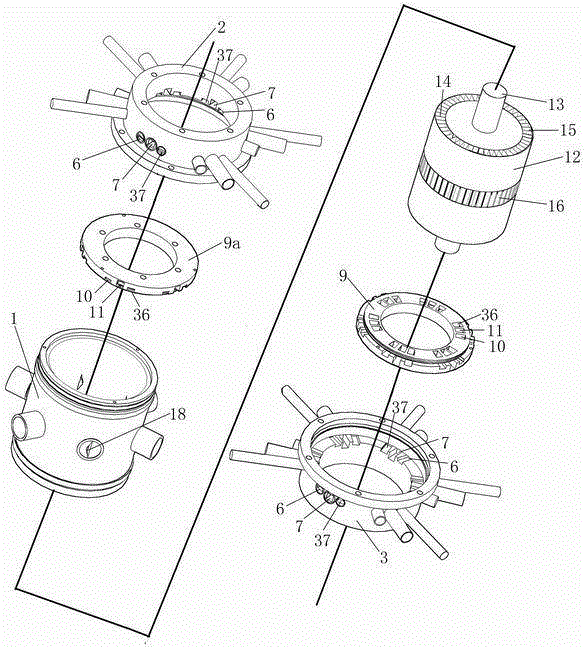
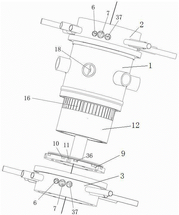
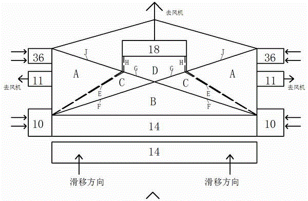
[0023] figure 1 , 2 A high-pressure gas-driven shock-impinging double-pressurized gas-wave supercharger is shown. The core is to use the double pressurization mechanism of shock wave and transmission shock wave to realize the high pressure ratio pressurization of the compressed gas, which is mainly composed of three parts: the main body, the upper body and the lower body. The main body includes a main body shell 1 and a drum 12 with a shock wave collision tube 14 evenly arranged in the circumferential direction. The shock wave collision tube 14 is fan-shaped in cross section, and has a square through hole 16 at a symmetrical position in the middle; the main body There are isosceles trapezoidal pressurized fluid outlets 18 uniformly distributed in the circumferential direction at the symmetrical position in the middle of the housing shell 1. The position of the square ...

Embodiment 2

[0026] Example 2 High-pressure saturated water flash drive shock wave collision double pressurized gas wave supercharger

[0027] figure 1 , 2 A high-pressure saturated water flash-driven shock wave collision double pressurized air wave supercharger is shown. The core is to use the double pressurization mechanism of the shock wave and the transmission shock wave to realize the high pressure ratio pressurization of the compressed steam. And the condensation phenomenon in the process of water vapor supercharging is used to realize the separation of high and low pressure fluids, which is mainly composed of three parts: the main body, the upper body and the lower body. The main body includes a main body shell 1 and a drum 12 with a shock wave collision tube 14 evenly arranged in the circumferential direction. The shock wave collision tube 14 is fan-shaped in cross section, and has a square through hole 16 at a symmetrical position in the middle; the main body There are isosceles...

Embodiment 3

[0030] Example 3 Structure-adjustable shock wave collision double pressurized air wave supercharger

[0031] figure 2 The high-pressure driving fluid nozzle 10, the low-pressure expansion fluid nozzle 11 and the low-pressure driven fluid nozzle 36 on the detachable nozzle distribution plate 9 of an adjustable shock wave collision double pressurized air wave supercharger are shown, and the upper body The shell, the high-pressure driving fluid inlet 6 on the lower body shell, the low-pressure expansion fluid outlet 7, the low-pressure driven fluid inlet 37 and the isosceles trapezoidal pressurized fluid outlet 18 on the main body shell 1 and the double-ended looper flange 5 relative to each other. Positional relationship. There are specific angles between the high-pressure driving fluid nozzle 10, the low-pressure expansion fluid nozzle 11 and the low-pressure driven fluid nozzle 36 in the first detachable nozzle distribution plate 9, which are related to different working con...


PUM


Abstract

The invention discloses a shock wave collision dual-supercharging-type wave pressure supercharger, and belongs to the technical field of refrigeration and evaporation. According to the wave pressure supercharger, a shock wave and transmission shock wave dual-supercharging mechanism is utilized, and the high-pressure ratio of compressed gas is increased. A main machine body, an upper machine body and a lower machine body are connected through dual-end loose flanges. The main machine body comprises a main machine body shell and a rotary drum, the middle symmetric position of the main machine body shell is provided with supercharging gas outlets distributed evenly and circumferentially, shock wave collision tubes are evenly distributed on the rotary drum circumferentially, and the middle symmetric position of the rotary drum is provided with a square hole outwards. The upper machine body and the lower machine body are symmetrically arranged relative to the main machine body and are each provided with a detachable nozzle distribution disc, wherein high-pressure driving fluid nozzles and low-pressure expansion fluid nozzle outlets are distributed on the nozzle distribution disc periodically and circumferentially. According to the wave pressure supercharger, by the adoption of the shock wave collision principle, the gas supercharging effect is greatly improved due to a middle isosceles trapezoid supercharging fluid outlet, the temperature increasing effect is remarkable, the pressure reduction and temperature decrease effects are obvious due to two-side low-pressure expansion fluid outlet gas, the gas hot separation speed is high, the effect is good, the machine body size is small, and the wave pressure supercharger is portable and easy to maintain.

Description

technical field [0001] The invention relates to a shock wave collision double boost type gas wave supercharger, which belongs to a supercharging device that provides high-pressure gas that meets requirements for fields such as refrigeration and evaporation. Background technique [0002] At present, the gas supercharging devices used in the field of refrigeration and evaporation mainly include compressors, ejectors and conventional gas wave superchargers. [0003] The compressor rotates through a high-speed turbine to convert the kinetic energy into the pressure energy of the gas, so as to achieve the purpose of gas boosting. Since the pressurization effect of the compressor is greatly affected by the type of medium, such as when compressing water vapor, the efficiency of the compressor becomes very low, and the vacuum water vapor compressor has a large size in the evaporation field. The ejector ejects the low-pressure airflow through the high-pressure driving airflow, and ...

Claims


Application Information

Patent Timeline
Patent Type & Authority Applications(China)
IPC IPC(8): F15B3/00
CPCF15B3/00
Inventor 代玉强胡大鹏邹久朋朱彻张斯亮武锦涛程永航陶盛洋
Owner DALIAN UNIV OF TECH
Why Eureka
Try Eureka