Engine and air inlet system thereof

A technology of air intake system and engine, which is applied in the direction of engine components, machine/engine, charging system, etc., can solve problems such as obstructed air flow, uneven air flow, engine intake fluctuations, etc., and achieves easy installation and disassembly, increased The pressure effect is obvious and the intake air volume is increased

Active Publication Date: 2016-07-27
SHANGHAI QINGCHE AUTOMOTIVE ENG CO LTD
View PDF5 Cites 11 Cited by
  • Summary
  • Abstract
  • Description
  • Claims
  • Application Information

AI Technical Summary

Problems solved by technology

[0008] In the existing electric turbocharger, since the intake of the turbine is connected in series to the main intake pipeline of the engine, the blades and the motor are arranged in the intake pipe. When the compressed air capacity cannot keep up with the intake demand or when the motor stops working, the impeller and the motor will hinder the flow of air in the pipeline, resulting in poor air flow, affecting the intake efficiency and the maximum torque of the engine
[0009] Moreover, the boosted intake air volume of the existing electric turbocharger is limited. This is because the existing electric turbocharger supercharges the air in the main intake pipe. Depends on the maximum intake capacity of the main pipe
[0010] In addition, due to the layout of the air outlet of the existing electric turbocharger, the air flow after the boost is uneven, and turbulent flow is easily formed, resulting in fluctuations in the intake air of the engine and engine surge

Method used


Image

  • Engine and air inlet system thereof
  • Engine and air inlet system thereof
  • Engine and air inlet system thereof

Examples


Embodiment Construction

[0051] Preferred embodiments of the present invention will be described in detail below with reference to the accompanying drawings, so as to better understand the purpose, features and advantages of the present invention. It should be understood that the embodiments shown in the drawings are not intended to limit the scope of the present invention, but only to illustrate the essence of the technical solutions of the present invention.

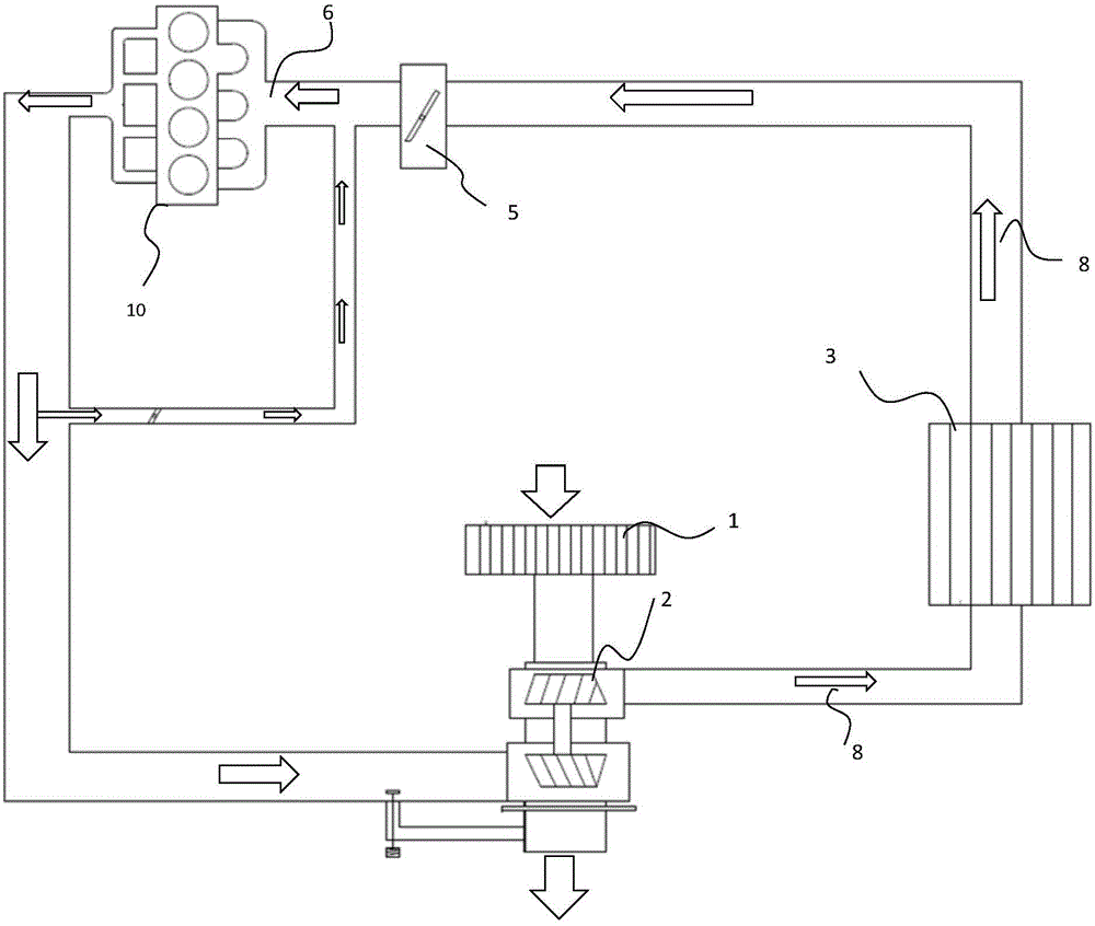
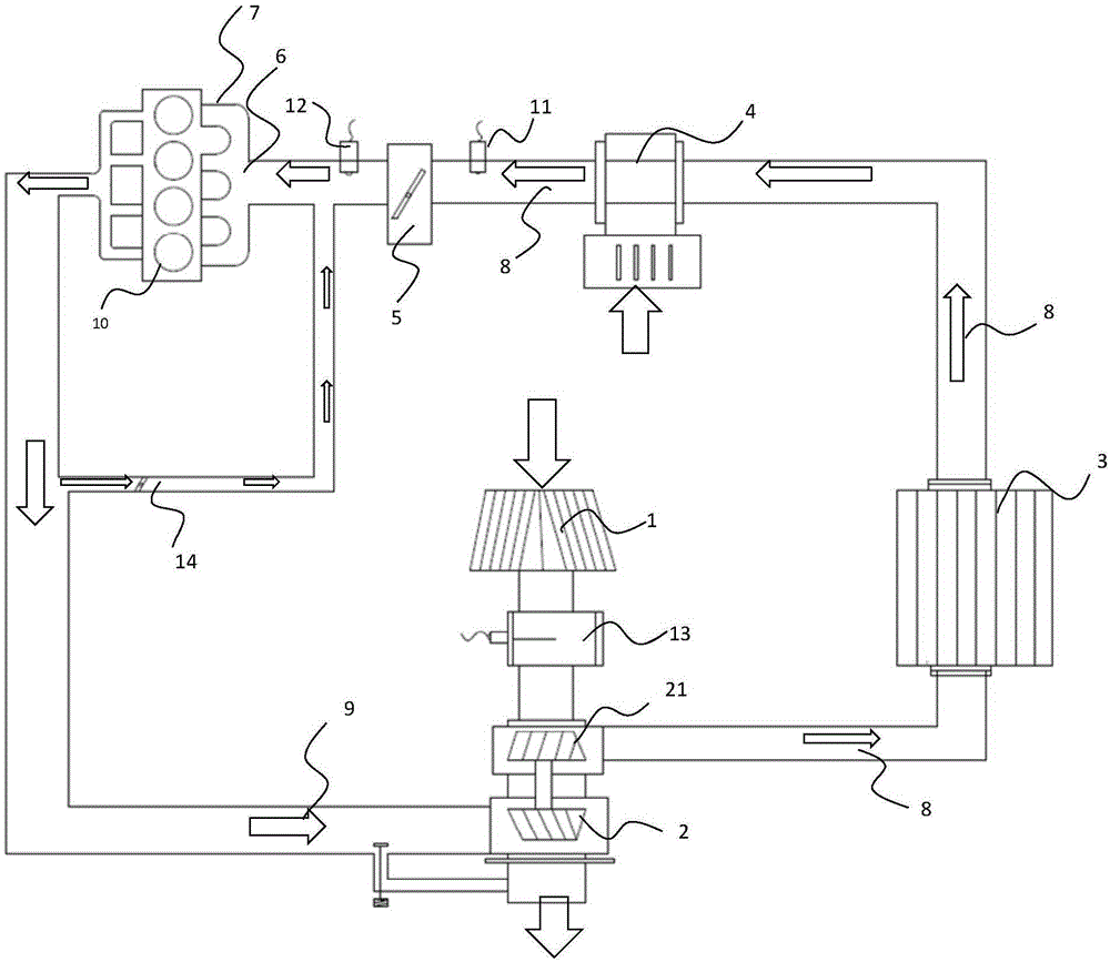
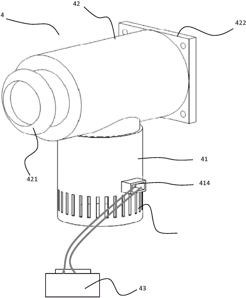
[0052] figure 2 is a schematic diagram of an engine air intake system 100 provided with an electric supercharger according to an embodiment of the present invention. Such as figure 2 As shown, the engine air intake system 100 includes an air filter 1, a turbocharger 2, an intercooler 3, an electric supercharger 4, an electronic throttle valve 5, an intake manifold main pipe 6, and an air intake system along the air intake direction. Gas manifold 7 and intake pipe 8 and exhaust pipe 9 connecting the above-mentioned components. Wherein, the...


PUM


Abstract

The invention discloses an engine and an air inlet system thereof. The air inlet system of the engine comprises an air inlet pipe, an air inlet manifold, an air inlet manifold header and an electric supercharger arranged on the air inlet pipe and located in front of the air inlet manifold header of the engine. The electric supercharger comprises a base, a motor arranged in the base, fan blades arranged in the base and a supercharging pipe communicated with the base through fluid. The base is provided with an air inlet, and the supercharging pipe is provided with an air outlet. The supercharging pipe is connected to the air inlet pipe in series and communicated with the air inlet pipe through fluid, and the motor can drive the fan blades to rotate, so that air flow flows in through the air inlet and flows out from the air outlet, and the air flow is mixed with air flowing in from the air inlet pipe to be sucked into an air cylinder of the engine together. By means of the engine and the air inlet system of the engine, emission can be effectively reduced, the efficiency of the engine is improved, the low-speed torque characteristics of the engine are improved, and engine surge is not caused.

Description

technical field [0001] The present invention relates to internal combustion engines, in particular to the field of internal combustion engine control based on oil-gas mixed combustion, including gasoline engine control, diesel engine control, natural gas and flexible fuel (mixture of methanol, ethanol, dimethyl ether and gasoline, etc.) Vehicle control and application of the above engines. Background technique [0002] The main purpose of internal combustion engine supercharging technology is to increase the intake air volume of the cylinder in a single combustion cycle by increasing the pressure of the internal combustion engine to inhale fresh air, thereby increasing the power and torque of the engine. The current mainstream supercharging methods include turbocharging (TurboBoost), mechanical supercharging, electric turbocharging, and hybrid supercharging system (turbo supercharging + mechanical supercharging or electric turbocharging). [0003] A turbocharger is an air c...

Claims


Application Information

Patent Timeline
Patent Type & Authority Applications(China)
IPC IPC(8): F02M35/10F02M31/04
Inventor 赵芸
Owner SHANGHAI QINGCHE AUTOMOTIVE ENG CO LTD
Why Eureka
Try Eureka