High-precision gas concentration detection method and detection apparatus thereof

A gas concentration detection and detection device technology, which is applied in the measurement of color/spectral characteristics, etc., can solve the problems of many influencing factors and inaccurate detection results, and achieve the effect of improving detection accuracy and eliminating influence.

Active Publication Date: 2015-04-22
青岛励精海洋科技有限公司
View PDF5 Cites 30 Cited by
  • Summary
  • Abstract
  • Description
  • Claims
  • Application Information

AI Technical Summary

Problems solved by technology

[0006] In order to solve the technical problems of many factors affected by the existing gas concentration detection method and inaccurate detection results, the present invention provides a method for improving the detection accuracy of the gas concentration of the tuned laser, which can solve the above problems

Method used


Image

  • High-precision gas concentration detection method and detection apparatus thereof
  • High-precision gas concentration detection method and detection apparatus thereof
  • High-precision gas concentration detection method and detection apparatus thereof

Examples


Embodiment 1

[0031] Embodiment one, see figure 1 As shown, a high-precision gas concentration detection method includes the following steps:

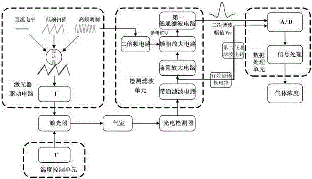
[0032] S1. The op-amp adder adds the low-frequency triangular wave scanning signal, high-frequency sine wave modulation signal and DC signal to the laser drive circuit as the current input of the laser drive circuit;

[0033] S2. The laser driving circuit drives the laser to emit a laser signal, passing through the measured gas in the gas chamber;

[0034] S3. The photoelectric detector receives the laser signal output after being absorbed by the relevant gas in the gas chamber and performs photoelectric detection, converts it into a voltage signal and inputs it to the detection filter unit;

[0035] S4. The detection filter unit performs band-pass filter processing on the converted voltage signal, and one of the output signals is sequentially processed by pre-amplification, phase-locked amplification, and low-pass filter to obtain the second harmo...

Embodiment 2

[0047] Embodiment 2, based on a high-precision gas concentration detection method in Embodiment 1, this embodiment provides a high-precision gas concentration detection device, such as figure 1 As shown, it includes a laser emitting device and a photodetector, the laser emitting device includes a laser drive circuit and a laser, the input end of the laser drive circuit is connected to an adder, and the photodetector is connected to a detection filter unit and a data processing unit connected, the detection filter unit includes a current-voltage conversion circuit, a band-pass filter circuit and a preamplifier circuit connected in sequence, one of the output ends of the band-pass filter circuit is sequentially connected with the preamplifier circuit, phase-locked The amplifying circuit is connected to the first low-pass filter circuit, and the other channel is connected to the effective value conversion circuit and the second low-pass filter circuit in sequence, and the output t...


PUM


Abstract

The invention discloses a high-precision gas concentration detection method and a detection apparatus thereof. The detection method comprises the following steps: a current is input to a laser drive circuit; a laser is driven by the laser driving circuit to emit a laser signal, and the laser signal passes through a detected gas in a gas chamber; a photoelectric detector receives a laser signal output by a relevant gas in the gas chamber after absorption, implements photoelectric detection, converts the laser signal to a voltage signal and inputs the voltage signal to a detection filter unit; a signal output by the detection filter unit implementing band-pass filter processing is divided into two paths, one path goes through a lock-in amplifier circuit to obtain a secondary harmonic signal, and the other path goes through an RMS conversion circuit to obtain an RMS signal; sampling is carried out, and the wave peak value Vpp max, the wave trough value Vpp min and the RMS are calculated; and a data processing unit calculates the concentration X of the gas to be detected. The gas concentration detection method can be used to accurately measure the concentration of the gas, and can eliminate the influences of a circuit and the change of light transmittance on the measurement of the concentration of the gas in order to improve the detection accuracy.

Description

technical field [0001] The invention belongs to the technical field of gas concentration detection, and in particular relates to a high-precision gas concentration detection method and a detection device. Background technique [0002] Spectral gas analysis technology reverses and analyzes the gas concentration by measuring the gas transmittance. Therefore, to accurately measure the measured gas concentration, the gas transmittance must be accurately measured. Factors such as dust, window pollution, and changes in laser power attenuation will change the light transmittance of the measured gas. To eliminate the influence of light transmittance, it is necessary to find a method that is synchronous and proportional to the peak-to-peak value of the second harmonic absorption when the light transmittance changes. The influence factor of the change, the absorption harmonic peak-to-peak value is divided by this factor to eliminate the influence of the transmittance change on the lin...

Claims


Application Information

Patent Timeline
Patent Type & Authority Applications(China)
IPC IPC(8): G01N21/39
Inventor 张可可郑学勇刘世萱齐勇赵强孙金伟李选群苗斌
Owner 青岛励精海洋科技有限公司
Why Eureka
Try Eureka