An Adaptive LED Driving Circuit

An LED driving and self-adaptive technology, applied in the direction of electric lamp circuit layout, electric light source, lighting device, etc., can solve the problems of reduced design flexibility of the whole lamp, small LED conduction angle, large harmonic distortion, etc., to avoid electromagnetic interference. Problems, control method circuit is simple, harmonic distortion reduction effect

Active Publication Date: 2017-10-31
GUANGZHOU PLEMAS LIGHTING CO LTD
View PDF7 Cites 0 Cited by
  • Summary
  • Abstract
  • Description
  • Claims
  • Application Information

AI Technical Summary

Problems solved by technology

The problem with this method is that the circuit is complex, there are many components, the cost is high, and the reliability is reduced; the second is that the volume becomes larger after the driving power is added, the design of the lamp body must consider the space for the driving power, and the design flexibility of the whole lamp is reduced; The third is that the circuit works in a high-frequency state of 30KHz-150KHz, which will inevitably produce electromagnetic interference; the fourth is that the driving power needs to use electrolytic capacitors, and electrolytic capacitors have a life limit, generally about 8000 hours, relatively speaking, the LED life can reach 30000 Hours or more, so the life of the driving power limits the life of the LED lamp, and many LED lamp failures are caused by power failures
[0003] In order to solve these problems, there are some AC drive LED circuits that do not need a driving power supply. Since the voltage of a single LED is generally about 3.2V, which is far lower than the mains voltage, multiple LEDs are used in series to make the total voltage close to the mains. Voltage, and then through the current limiting circuit (current limiting resistor) to make the LED work, such as figure 1 shown, when the input voltage is less than V d (It is the sum of the voltages of multiple LEDs in series) when the LED is in the cut-off state and does not emit light, the LED turns on and emits light when it is greater than Vd. The disadvantages of this circuit are that the LED conduction angle is small, the stroboscopic is more obvious, and the electrical efficiency is low. Very high harmonic distortion

Method used


Image

  • An Adaptive LED Driving Circuit
  • An Adaptive LED Driving Circuit
  • An Adaptive LED Driving Circuit

Examples


Embodiment 1

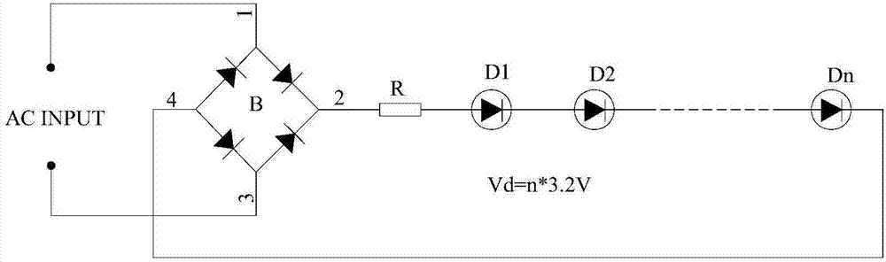
[0040] Please refer to figure 2 As shown, since the voltage of a single LED is generally about 3.2V, this case uses multiple low-voltage LEDs in series or directly uses high-voltage lamp beads to form an LED series circuit. A single high-pressure lamp is an LED string.

[0041] The principle diagram of this case is as follows:

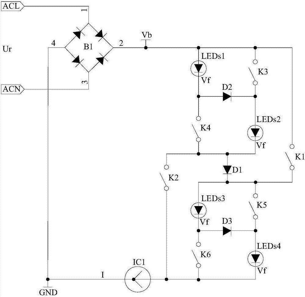
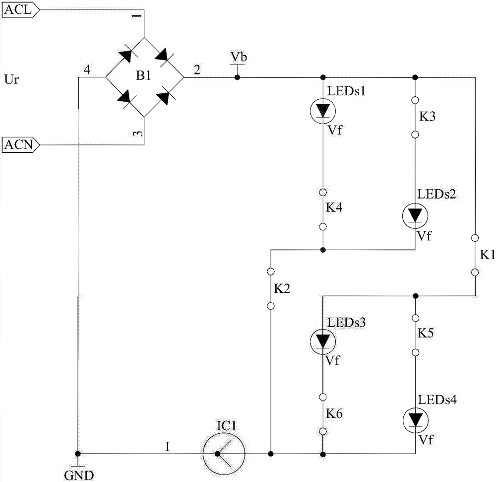
[0042] figure 2 Among them, B1 is a rectifier bridge stack, which rectifies the mains power into a fluctuating DC voltage Vb; LEDs1 to LEDs4 are four LED strings, and their total forward voltage is Vf; K1 to K6 are 6 current control switches composed of circuits. It is a normally closed switch, the state of the switch is controlled by the current of the circuit, the switch is closed when the current is small, and the switch is open when the current is large, and the trigger current of its disconnection can be controlled by the parameter value of the component, and the parameter value of the circuit component is set so that The trigger current of K...

Embodiment 2

[0069] Embodiment 2 is to increase one or more current control sub-units on the basis of embodiment 1. When adding a current control sub-unit, a structure consisting of 6 LED strings is formed, and the added current control sub-units can be visualized In order to be placed between the two current control subunits of Embodiment 1, a diode is connected to the input and output ends of the added current control subunit respectively, so as to be connected to the two current control subunits of Embodiment 1 respectively , at the same time, a current control switch is also connected in series at the input and output terminals of the added current control subunit, please refer to Figure 10 As shown, the trigger currents of the current control switches are as follows from small to large: K1 (K2, K15, K16), K3 (K4), K17 (K18), K5 (K6). The specific working principle is similar to that of the first embodiment, and will not be repeated here. Of course, if more current control subunits a...

Embodiment 3

[0071] The third embodiment is to add one or more current control circuits on the basis of the first embodiment, please refer to Figure 11 As shown, when adding a current control circuit, the added current control circuit is connected in parallel with the previous current control circuit, and then a current control switch K13 is added at the input end of the two, and a current control switch K13 is connected in series at the output end of the previous current control circuit The current control switch K14, at the same time, a diode D7 is connected between the output terminal of the previous current control circuit and the added current control circuit, so as to expand into a structure composed of 8 LED strings, the current control switches K13, K14 and the current control The switch K1 etc. have the same structure. The trigger current of the current control switch is K1 (K2, K7, K8), K3 (K4), K5 (K6), K9 (K10), K11 (K12) from small to large, and the trigger current of the cur...


PUM


Abstract

The invention discloses an adaptive LED driving circuit, which comprises: a fluctuating DC power supply, used to generate a DC voltage signal with periodic voltage changes; a current control circuit, used to change the series and parallel relationship between LED strings, so as to Adaptive to the periodic change of the DC signal; a current limiting or constant current circuit, used to limit or constant current the DC voltage signal, and drive the current control circuit to run; the fluctuating DC power supply, the current control circuit and the current limiting Or the constant current circuit is connected in series to form a closed loop; the current control circuit includes at least two current control subunits, and each current control subunit includes a first normally closed switch, a second normally closed switch, a fourth normally closed switch, a a diode and a second diode. The LED strings of the present invention can be connected in parallel or in series through a normally closed switch according to the input voltage level and the magnitude of the circuit current, thereby changing the total voltage of the LED strings and automatically adapting to changes in the input voltage.

Description

technical field [0001] The invention relates to LED lighting tools, in particular to an adaptive LED drive circuit which changes the series-parallel structure of its own LED strings as the input voltage changes. Background technique [0002] At present, LED lighting is very popular. LED is a constant voltage device, and its current and voltage characteristics are similar to diodes. Therefore, it is necessary to limit the LED to work within the allowable current range to avoid LED damage due to overcurrent. Generally, LED lamps are driven by a DC power supply. The mains power is converted into DC power by a high-frequency switching power supply to drive the LED to emit light. The constant current circuit makes the LED work within a safe current range. The problem with this method is that the circuit is complex, there are many components, the cost is high, and the reliability is reduced; the second is that the volume becomes larger after the driving power is added, the design ...

Claims


Application Information

Patent Timeline
Patent Type & Authority Patents(China)
IPC IPC(8): H05B37/02
Inventor 潘伟雄
Owner GUANGZHOU PLEMAS LIGHTING CO LTD
Why Eureka
Try Eureka