Limit migration of target material

一种电子靶、导电元件的技术,应用在X射线管靶材料、X射线管的零部件、X射线管靶和转换器等方向,能够解决减少使用寿命等问题

Active Publication Date: 2017-03-29
EXCILLUM
View PDF4 Cites 0 Cited by
  • Summary
  • Abstract
  • Description
  • Claims
  • Application Information

AI Technical Summary

Problems solved by technology

Free particles (including debris and vapors from liquid targets) tend to gradually degrade the cathode (e.g., through corrosion) and reduce its useful life

Method used


Image

  • Limit migration of target material
  • Limit migration of target material
  • Limit migration of target material

Examples


Embodiment Construction

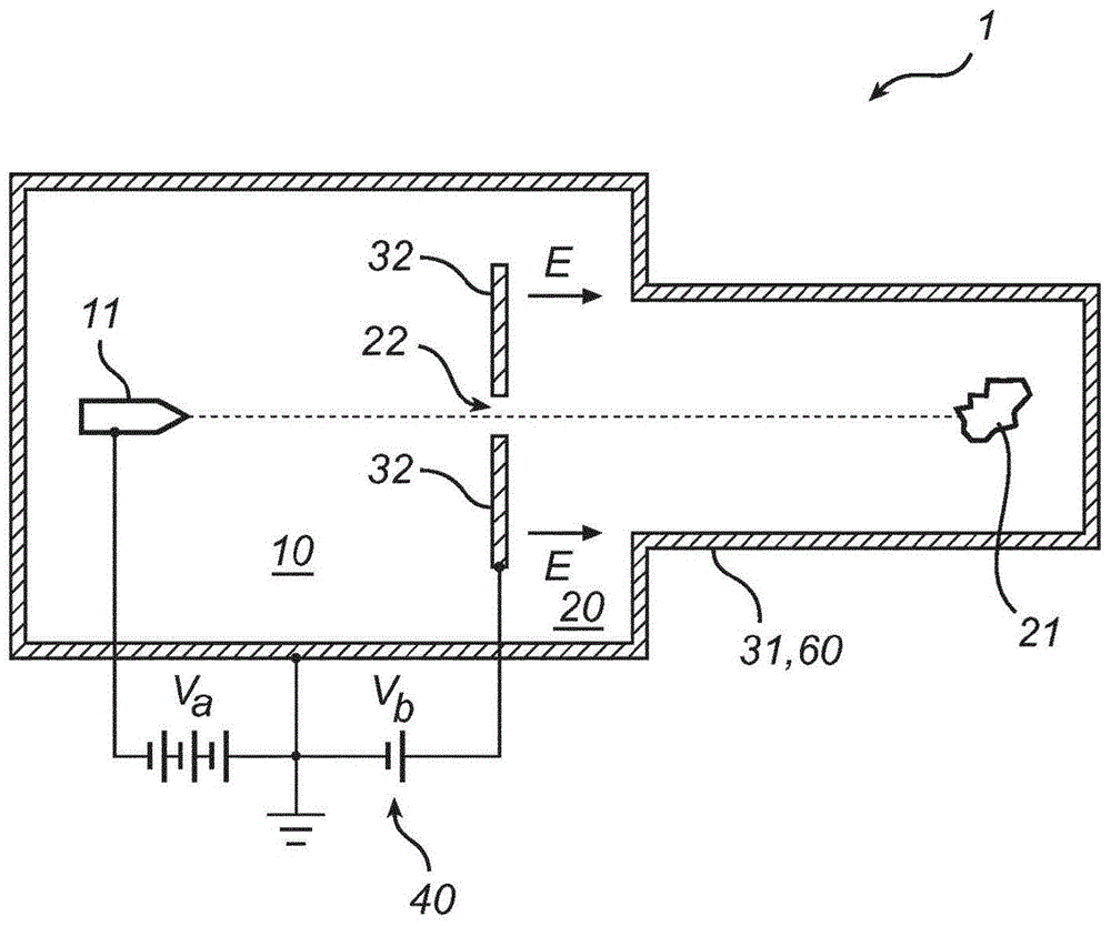
[0064] figure 1 Shown is an electron irradiation system 1 configured to generate an electron beam that irradiates a target in an irradiation site 21 located in the right part of the system. The electron beam is generated by the high voltage cathode 11 in the electron gun located in the left part of the system, which is connected to the accelerating voltage V a . The accelerating voltage can be on the order of tens of kilovolts or hundreds of kilovolts. These components are contained in a gas-tight enclosure 60, which can be evacuated to allow vacuum or quasi-vacuum conditions (such as 10 -9 and 10 -6 The generation, propagation and irradiation of electron beams take place between bars. In the present embodiment, the airtight housing 60 is formed as the first conductive member 31, which is electrically connected to the ground potential. The first conductive element 31 may comprise a plurality of subcomponents, which are combined into a conductive form. A second conductive...


PUM


Abstract

In the electron irradiation system (1), an airtight casing (60) surrounds a cathode region (10) and an irradiation region (20), which are communicated through at least one hole (22). In the cathode region, a high-voltage cathode (11) for emitting electron beams is arranged. In the irradiation area there is an irradiation site (21) arranged to accommodate stationary or moving targets to be irradiated. The migration of cathode degraded fragments is restricted by means of an electric field (E) designed to prevent positively charged particles from entering the cathode region through the pores. The invention can be embodied by an axial electric field which achieves an energy threshold, or a transverse field which deflects charged particles away from the trajectory introduced into the cathode region.

Description

technical field [0001] The invention disclosed herein relates generally to electron irradiation systems. In particular, it concerns electron-impinging X-ray sources with cathodic protection. Background technique [0002] Systems for generating X-rays by irradiating a liquid target are described in the Applicant's International Applications PCT / EP2009 / 000481, PCT / EP2009 / 002464, PCT / EP2010 / 068843 and PCT / SE2011 / 051557. In these systems, which typically operate at very low pressures, an electron gun comprising a high voltage cathode is utilized to generate an electron beam that strikes the target. Free particles, including debris and vapor from the liquid target, tend to gradually degrade the cathode (eg, by corrosion) and reduce its useful life. Similar problems related to chemical cathode degradation have been noted in high energy electron irradiation systems with cathodes operating at high potentials and / or high temperatures. Contents of the invention [0003] In view o...

Claims


Application Information

Patent Timeline
Patent Type & Authority Patents(China)
IPC IPC(8): G21K5/04H01J35/04
CPCH01J35/04H01J2235/082H01J2235/16H01J35/116H01J35/147H01J29/62G21K1/08G21K5/04
Inventor 奥斯卡·汉伯格汤米·图希玛波尔·塔克曼
Owner EXCILLUM
Why Eureka
Try Eureka