Multi-cell single voltage electrolysis apparatus and method of using same

a single-voltage electrolysis and multi-cell technology, applied in the field of high-efficiency electrolysis systems, can solve the problems of limited regional availability, dire consequences for the world's economy, and its vulnerability to disruption of the supply of energy, and achieve the effect of high output efficiency

Inactive Publication Date: 2008-12-04
KUZO HLDG
View PDF16 Cites 6 Cited by
  • Summary
  • Abstract
  • Description
  • Claims
  • Application Information

AI Technical Summary

Benefits of technology

[0008]The present invention provides a method and apparatus for achieving high output efficiency from an electrolysis system using a plurality of electrolysis cells all located within a single electrolysis tank. Each individual electrolysis cell includes a membrane which separates the portion of the electrolysis tank containing that electrolysis cell into two regions. Additionally, each electrolysis cell includes a plurality of metal members and a plurality of high voltage electrodes. The plurality of metal members includes at least a first and second metal member containe

Problems solved by technology

Unfortunately in a world of rapidly increasing energy needs, dependence on any energy source of finite size and limited regional availability has dire consequences for the world's economy.
In particular, as a country's need for energy increases, so does its vulnerability to disruption in the supply of that energy.
Additionally, as fossil fuels are the largest single source of carbon dioxide emissions, a greenhouse gas, continued reliance on such fuels can be expected to lead to continued global warming.
This process is well developed, but due to its reliance on fossil fuels and the release of carbon dioxide during pr

Method used


Image

  • Multi-cell single voltage electrolysis apparatus and method of using same
  • Multi-cell single voltage electrolysis apparatus and method of using same
  • Multi-cell single voltage electrolysis apparatus and method of using same

Examples


Embodiment Construction

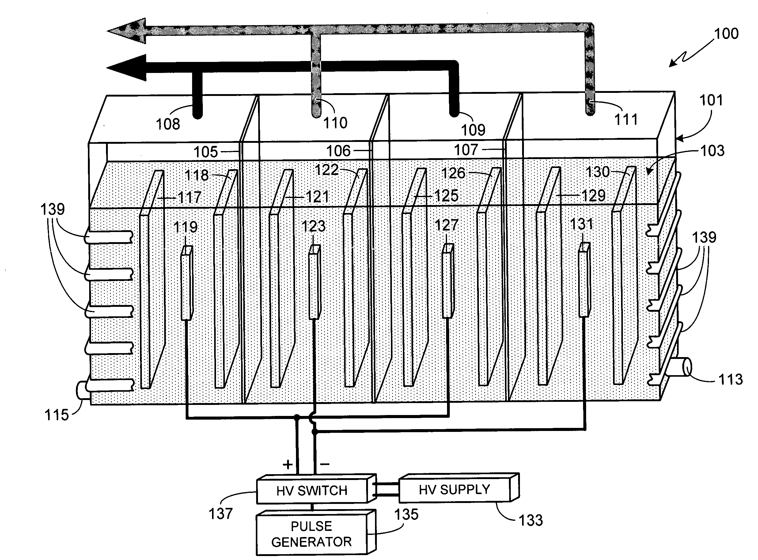
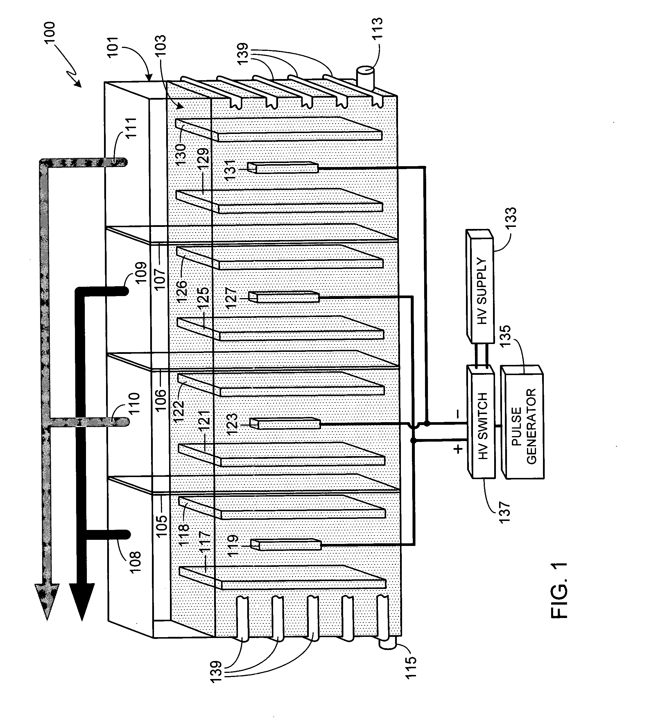
[0027]FIG. 1 is an illustration of an exemplary, and preferred, embodiment of the invention which can be used, for example, as a heat generator. Electrolysis system 100 includes a tank 101 comprised of a non-conductive material, the size of the tank depending primarily upon the desired output level for the system, for example the desired heat production. Although tank 101 is shown as having a rectangular shape, it will be appreciated that the invention is not so limited and that tank 101 can utilize other shapes, for example cylindrical, square, irregularly-shaped, etc. Tank 101 is substantially filled with liquid 103. In at least one preferred embodiment, liquid 103 is comprised of water with an electrolyte, the electrolyte being either an acid electrolyte or a base electrolyte. Exemplary electrolytes include potassium hydroxide and sodium hydroxide. The term “water” as used herein refers to water (H2O), deuterated water (deuterium oxide or D2O), tritiated water (tritium oxide or T...


PUM

PropertyMeasurementUnit
Fractionaaaaaaaaaa
Fractionaaaaaaaaaa
Percent by massaaaaaaaaaa

Abstract

A method and apparatus for achieving high output efficiency from an electrolysis system (100) using a plurality of electrolysis cells all located within a single electrolysis tank (101) is provided. Each individual electrolysis cell includes a membrane (105-107), a plurality of metal members comprised of at least a first and second metal member (117/118; 125/126) and at least a third and fourth metal member (121/122; 129/130), and a plurality of high voltage electrodes comprised of at least an anode (119; 127) and a cathode (123; 131). Within each cell, the high voltage anode is interposed between the first and second metal members and the high voltage cathode is interposed between the third and fourth metal members. The high voltage applied to the high voltage electrodes is pulsed.

Description

CROSS-REFERENCE TO RELATED APPLICATION[0001]Under 35 U.S.C. 119, the present application claims the benefit of the earlier filing date and the right of priority to Canadian Patent Application Serial No. 2,590,421, filed May 30, 2007, the disclosure of which is hereby incorporated by reference for any and all purposes.FIELD OF THE INVENTION[0002]The present invention relates generally to electrolysis systems and, more particularly, to a high efficiency electrolysis system and methods of using same.BACKGROUND OF THE INVENTION[0003]Fossil fuels, in particular oil, coal and natural gas, represent the primary sources of energy in today's world. Unfortunately in a world of rapidly increasing energy needs, dependence on any energy source of finite size and limited regional availability has dire consequences for the world's economy. In particular, as a country's need for energy increases, so does its vulnerability to disruption in the supply of that energy. Additionally, as fossil fuels are...

Claims


Application Information

Patent Timeline
IPC IPC(8): C25B15/00C25B1/00C25B9/10C25B9/23
CPCC25B1/04C25B9/00C25B15/00Y02E60/366Y02E60/36
Inventor DAVIDSON, NEHEMIA
Owner KUZO HLDG
Why Eureka
Try Eureka