Limiting migration of target material

a target material and target material technology, applied in the field of limiting the migration of target material, can solve the problems of reducing the useful so as to increase the life of the cathode, and reduce the migration rate of the target material.

Active Publication Date: 2015-06-25
EXCILLUM
View PDF1 Cites 6 Cited by
  • Summary
  • Abstract
  • Description
  • Claims
  • Application Information

AI Technical Summary

Benefits of technology

[0003]In view of the above shortcomings of available technology, it is an object of the present invention to propose a high-energy electron irradiation system with an increased cathode life. A particular object is to provide an e...

Problems solved by technology

Free particles, including debris and vapour from the liquid target, tend to gradually degrade the cathode (e.g., by corrosion) and reduce its useful life.
Similar problems associated with chemical cathode degradation have been noted in high-energy electron irradiation systems with cathodes operating at a high potential and/or high temperature.
Conversely, because the electrons in the electron beam typically travel much faster than the charged particles, it will be a more delicate task to design a magne...

Method used


Image

  • Limiting migration of target material
  • Limiting migration of target material
  • Limiting migration of target material

Examples


Embodiment Construction

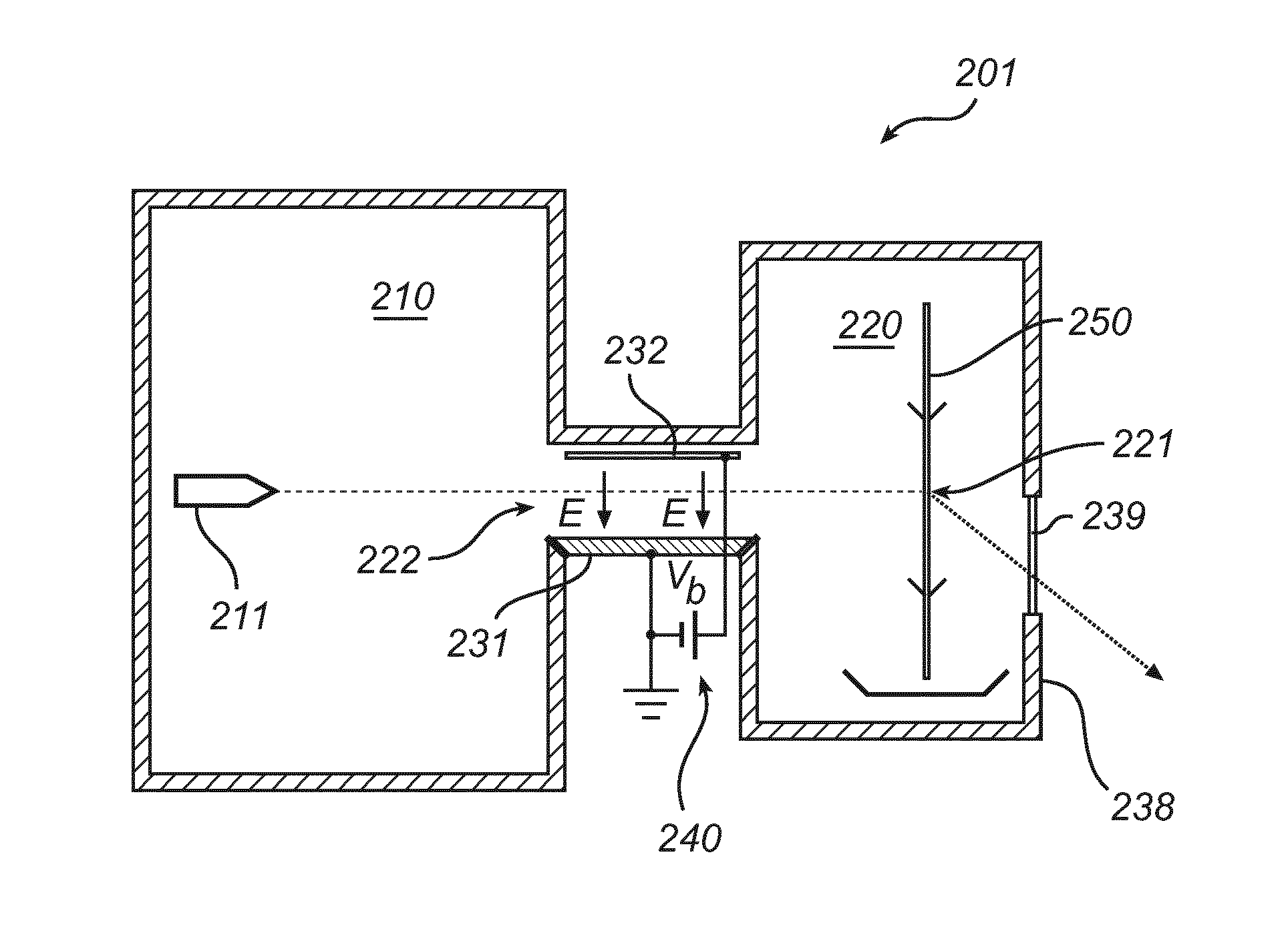
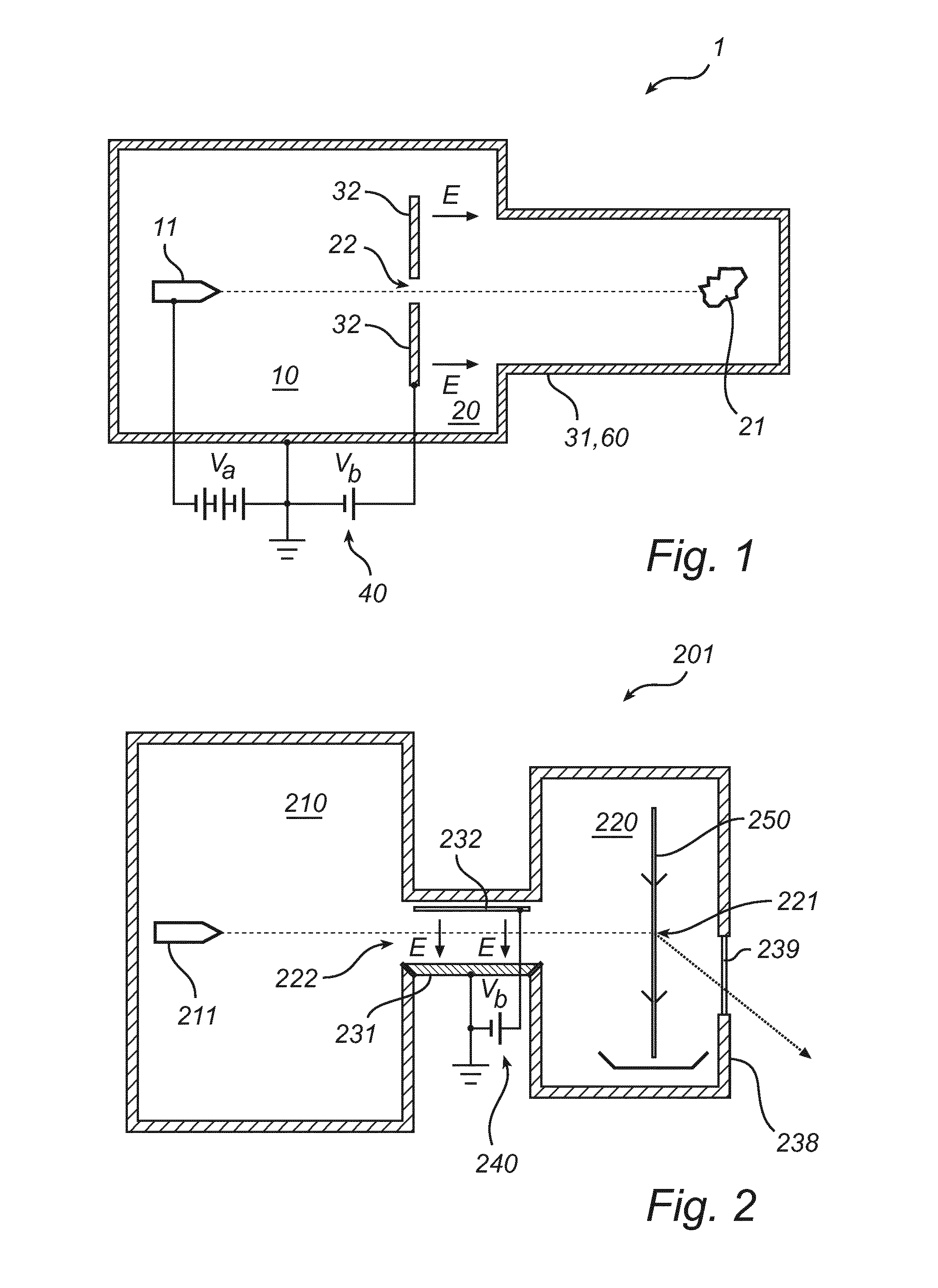
[0036]FIG. 1 shows an electron irradiation system 1 configured to produce an electron beam irradiating an object located in an irradiation site 21 in the right-hand portion of the system. The electron beam is produced by a high-voltage cathode 11 in an electron gun located in the left-hand portion of the system, which is connected to an acceleration voltage Va. The acceleration voltage may be of the order of tens of kilovolts or hundreds of kilovolts. These parts are contained in a gas-tight housing 60, which can be evacuated to allow the electron beam generation, propagation and irradiation to take place in vacuum or quasi-vacuum conditions, such as between 10−9 and 10−6 bar. In this embodiment, the gas-tight housing 60 is formed as a first conductive element 31, which is electrically connected to ground potential. The first conductive element 31 may consist of a plurality of subparts which are combined in an electrically conductive fashion. A second conductive element 32, which is...


PUM


Abstract

In an electron irradiation system, a gas-tight housing encloses a cathode region and an irradiation region, which communicate through at least an aperture. In the cathode region, there is arranged a high-voltage cathode for emitting an electron beam. In the irradiation region, there is an irradiation site arranged to accommodate a stationary or moving object to be irradiated. The migration of cathode-degrading debris is limited by means of an electric field designed to prevent positively charged particles from entering the cathode region via the aperture. The invention can be embodied with an axial electric field, which realizes an energy threshold, or a transversal field which deflects charged particles away from trajectories leading into the cathode region.

Description

TECHNICAL FIELD[0001]The invention disclosed herein generally relates to electron irradiation systems. In particular, it relates to an electron-impact X-ray source with a cathode protection arrangement.TECHNICAL BACKGROUND[0002]Systems for generating X rays by irradiating a liquid target are described in the applicant's International Applications PCT / EP2009 / 000481, PCT / EP2009 / 002464, PCT / EP2010 / 068843 and PCT / SE2011 / 051557. In these systems, which typically operate at very low pressures, an electron gun comprising a high-voltage cathode is utilized to produce an electron beam which impinges on the target. Free particles, including debris and vapour from the liquid target, tend to gradually degrade the cathode (e.g., by corrosion) and reduce its useful life. Similar problems associated with chemical cathode degradation have been noted in high-energy electron irradiation systems with cathodes operating at a high potential and / or high temperature.SUMMARY[0003]In view of the above short...

Claims


Application Information

Patent Timeline
IPC IPC(8): H01J29/62G21K1/08G21K5/04H01J35/08H01J35/14
CPCH01J29/62H01J35/08H01J2235/082G21K5/04G21K1/08H01J35/14H01J35/04H01J2235/16H01J35/116H01J35/147
Inventor HEMBERG, OSCARTUOHIMAA, TOMITAKMAN, PER
Owner EXCILLUM
Why Eureka
Try Eureka