Method to control the emission of a beam of electrons in a cathode, corresponding cathode, tube and imaging system

a technology of electron beam and emission device, which is applied in the direction of x-ray tube multi-cathode assembly, electrical discharge tube, x-ray tube, etc., can solve the problems of filament breaking, cathode subject to various contradictory constraints, and increase in temperature to the detriment of so as to reduce the focal spot of an electron beam, extend the lifetime of the emission device, and reduce the effect of the focal spo

Active Publication Date: 2013-07-30
GENERAL ELECTRIC CO
View PDF27 Cites 0 Cited by
  • Summary
  • Abstract
  • Description
  • Claims
  • Application Information

AI Technical Summary

Benefits of technology

[0025]One advantage of the invention is to propose a solution allowing simultaneous control over fluoro emission mode and control over the reduced size of the focal spot of an electron beam. Therefore with the invention it is notably possible to obtain an emission device capable of emitting a beam of electrons in fluoro emission mode, the focal spot of the electron beam being controlled so that it lies in the ranges of between 1.0 mm and 1.5 mm, 0.7 mm and 1.2 mm or 0.4 mm and 0.8 mm.
[0026]The invention also provides an emission device capable of emitting an electron beam in fluoro emission mode, the focal spot of the electron beam able to be controlled so that it lies between 0.4 mm and 0.8 mm or 0.1 mm and 0.5 mm.
[0027]A further advantage of the invention is to propose a solution which extends the lifetime of the emission devices. In particular, the invention proposes the use of a cathode comprising first and second emission devices, the two devices being capable of emitting an electron beam in fluoro emission mode, the focal spot of the electron beam being controlled so that it lies between 0.4 mm and 0.8 mm. Therefore, the two emission devices can be used alternately for the same application which extends the lifetime of the cathode. Additionally, the emission temperature of each of the two emission devices can be increased without reducing the lifetime of the cathode, since said cathode is based on the alternate use of the two emission devices which reduces the utilization and hence the wear of each device.
[0028]A further advantage of the invention is to propose a solution allowing increased emission to be reconciled with a reduced focal spot size of an electron beam. Therefore, the invention notably proposes an emission device comprising a large filament, emitting a beam of electrons whose focal spot lies between 1.0 mm and 1.5 mm, capable of emitting an electron beam with a smaller focal spot (between 0.4 mm and 0.8 mm) which allows increased emission temperature to be reconciled with a reduction in focal spot size. Additionally, the large filament better withstands increased emission than a small filament in terms of lifetime.
[0029]Finally, a further advantage of the invention is to propose a flexible solution allowing various modes of utilization of the emission devices in diverse applications. The invention particularly proposes a cathode comprising one or more emission devices for which simultaneous control is possible over fluoro or record emission mode and over reducing the size of the electron beam focal spot, which allows various fluoro or record emission modes to be obtained whose electron beams have different sized focal spots. The invention also proposes an emission device capable of emitting a beam of electrons in fluoro emission mode, for which the size of the focal spot is controlled so that it lies between 0.1 mm and 0.5 mm, this type of beam being of particular advantage for neurological observation.

Problems solved by technology

The design of the cathode is subject to various contradictory constraints, depending upon the use made of the associated imaging system.
Evidently, the increase in temperature is made to the detriment of the lifetime of the emission device, whose filament may finally break after evaporation at high temperature.
However, no cut-off voltage is applied to the focusing cup, which may generate remanent radiation for the patient since the cut-off of the high acceleration voltage is not instantaneous.
One disadvantage of prior art solutions is that they do not offer emission devices allowing simultaneous active reducing of focal spot size and a fluoro emission mode.
These solutions are therefore not flexible, and since the fluoro mode is used for long periods and is the most utilized mode in the imaging system, the small filament emission device is given intensive use, which reduces its lifetime.
Another drawback of some prior art solutions is that they do not allow the reconciling of high emission temperature to obtain good image quality (which generally assumes the use of a large filament) with the obtaining of a small-size focal spot, also to ensure good image resolution, whilst maintaining a long lifetime of the emission device.

Method used


Image

  • Method to control the emission of a beam of electrons in a cathode, corresponding cathode, tube and imaging system
  • Method to control the emission of a beam of electrons in a cathode, corresponding cathode, tube and imaging system
  • Method to control the emission of a beam of electrons in a cathode, corresponding cathode, tube and imaging system

Examples


Embodiment Construction

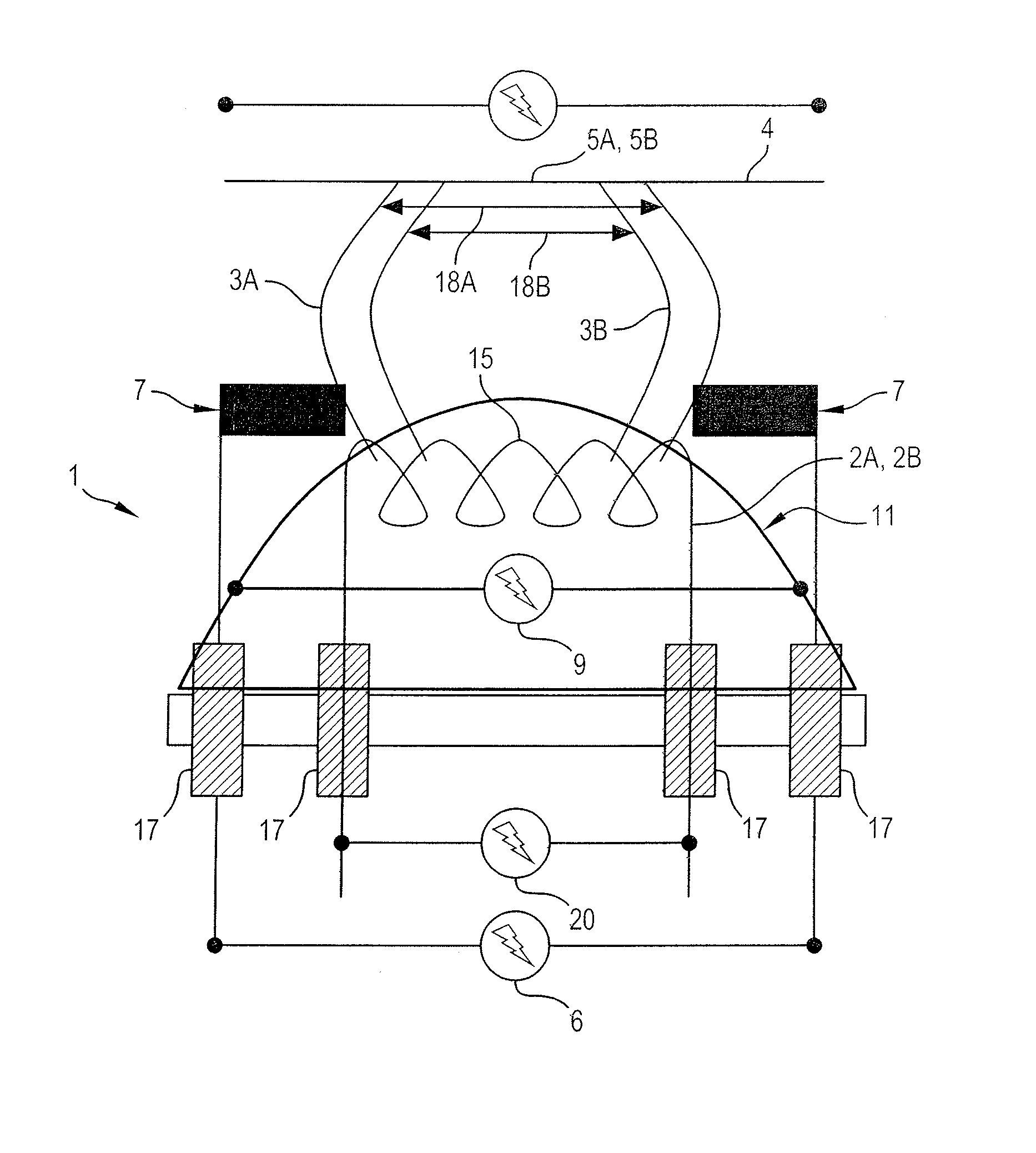
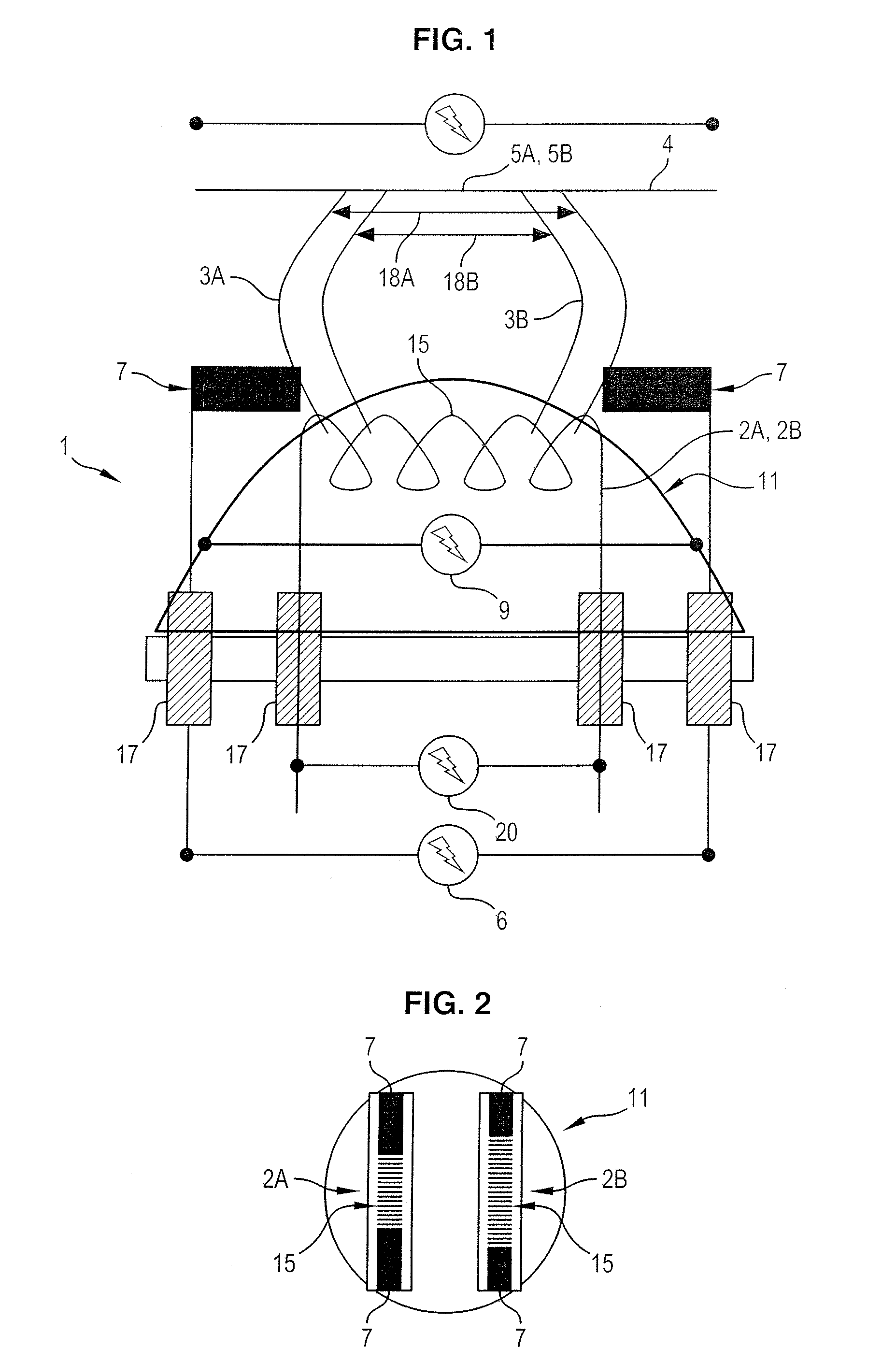
[0034]FIGS. 1 and 2 show a diagram of a cathode 1 according to the invention.

[0035]The cathode 1 comprises at least one emission device 2A capable of emitting a beam of electrons 3A. The cathode 1 comprises as many emission devices as required.

[0036]In general, the emission device 2A comprises an emission filament 15, in which an electric current of several amperes is passed (e.g. 6 amperes) to heat said emission filament 15, which allows generation of a beam 3A of electrons. The filament 15 is heated to high temperature, higher than 2000° C. The filament 15 is typically a coiled tungsten wire.

[0037]The beam 3A of electrons is accelerated in the vacuum towards an anode 4. Acceleration of the beam is obtained by applying an electric voltage difference between the cathode 1 and the anode 4.

[0038]One solution consists of applying a negative acceleration voltage 20 in the order of −75 kV to the emission device 2A, and a positive electric voltage in the order of +75 kV to the anode 4, th...


PUM


Abstract

A method for controlling emission of a beam of electrons in an X-ray imaging tube. The X-ray imaging tube has an anode and a cathode. The method comprises a step in which at least one emission device included in the cathode emits an accelerated incident beam of electrons onto an impact focal spot on the anode to generate X-rays. An emission device is associated firstly with an assembly of polarizing plates and secondly with a focusing cup. An electric generator simultaneously applies a beam focusing voltage to the assembly and / or to the cup to control a characteristic dimension of the focal spot, and a cut-off voltage to the cup to control the emission of the beam by the device. The invention also concerns a corresponding cathode, tube and imaging system.

Description

CROSS-REFERENCE TO RELATED APPLICATION[0001]This application claims priority under 35 U.S.C. §119(a)-(d) or (f) to prior-filed, co-pending French application number 0954636, filed on Jul. 6, 2009, which is hereby incorporated by reference in its entirety.BACKGROUND OF THE INVENTION[0002]1. Field of Invention[0003]The invention concerns a method to control the emission of an electron beam in an X-ray imaging tube. The invention also concerns an electron-emitting cathode, a tube, and an X-ray imaging system to implement said method.[0004]2. Description of Related Art[0005]In known X-ray imaging systems, such as scanners for medical applications, an imaging tube emits X-rays which pass through an object to be observed, e.g. part of a patient's body, said X-rays then being detected by an array of detectors which allows an image of the object to be constructed.[0006]Imaging tubes generally consist of a cathode capable of emitting an incident beam of electrons onto an impact focal spot on...

Claims


Application Information

Patent Timeline
Patent Type & Authority Patents(United States)
IPC IPC(8): H01J35/06H01J35/30H01J35/14
CPCH01J35/06H01J35/14H05G1/56H05G1/58H01J2235/068H01J35/147H01J35/066
Inventor LEMARCHAND, GWENAELDAHAN, FREDERICGAUDIN, CHRISTELLE
Owner GENERAL ELECTRIC CO
Why Eureka
Try Eureka