
Structure of hard-tube anti-fog endoscope

An endoscope and anti-fog technology, which is applied in the field of minimally invasive medical treatment, can solve the problems of reducing the optical imaging quality of the endoscope system, affecting the imaging quality of the endoscope system, etc., and achieves good window heat transfer performance and good infrared absorption performance. , to ensure the effect of image quality

Active Publication Date: 2015-04-29
QINGDAO O MEC MEDICAL TECH
View PDF7 Cites 10 Cited by
  • Summary
  • Abstract
  • Description
  • Claims
  • Application Information

AI Technical Summary

Problems solved by technology

[0002] In the invention patent "A device and method for an anti-fog endoscope system" with the application number of 201210324982.0, a method for realizing an anti-fog endoscope is proposed. One of the cores of the technical solution is to apply a transparent Visible light and the front optical window absorbing infrared light are packaged at the front end of the endoscope. After verification, it is found that this method has a good anti-fog effect, but due to the surface reflection of the front window, there will be light emitted from the light guide fiber bundle. The visible light emitted from the surface is directly reflected from the front window and enters the endoscope optical system to form stray light, which affects the imaging quality of the endoscope system
Therefore, it is necessary to improve the structure of the front window to overcome the defects of reducing the optical imaging quality of the endoscope system caused by the existing front window structure while ensuring the anti-fog function

Method used


Image

  • Structure of hard-tube anti-fog endoscope
  • Structure of hard-tube anti-fog endoscope
  • Structure of hard-tube anti-fog endoscope

Examples


Embodiment 1

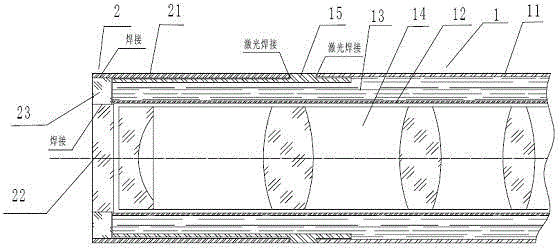
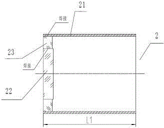
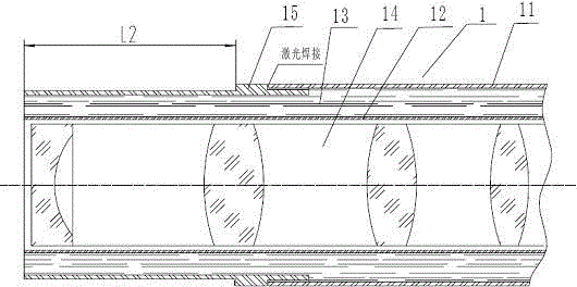
[0018] The matching gap between the outer diameter of the left and right sides of the connecting ring 15 and the inner diameter of the outer tube 11 is 0.01 mm, and the matching gap between the inner diameter of the sleeve 21 and the left outer diameter of the connecting ring 15 is 0.01 mm. The inner circle of the sleeve 21 is metallized within a range of 3 mm from the left end face to the left end face, the thickness of the optical window 22 is 0.7 mm, and the diameter of the metallized outer circle is 0.07 mm smaller than the inner diameter of the inner tube 12 , the thickness of the optical fiber window 23 is 0.65mm, the metallized outer diameter of the optical fiber window 23 and the metallized inner diameter of the sleeve 21 cooperate with a gap of 0.01mm, the metallized optical fiber window 23 The matching gap between the inner diameter of the optical window plate 22 and the metallized outer diameter of the optical window plate 22 is 0.01 mm, the value of L1 of the sleeve...

Embodiment 2

[0021] The matching gap between the outer diameter of the left and right sides of the connecting ring 15 and the inner diameter of the outer tube 11 is 0.02 mm, and the matching gap between the inner diameter of the sleeve 21 and the left outer diameter of the connecting ring 15 is 0.02 mm. The inner circle of the sleeve 21 is metallized within a range of 5 mm from the left end face to the left end face, the thickness of the optical window 22 is 1 mm, and the diameter of the metallized outer circle is 0.1 mm smaller than the inner diameter of the inner tube 12, The thickness of the optical fiber window 23 is 0.9mm, the metallized outer diameter of the optical fiber window 23 and the metallized inner diameter of the sleeve 21 have a matching clearance of 0.02mm, and the metallized outer diameter of the optical fiber window 23 is The matching gap between the inner diameter and the metallized outer diameter of the optical window 22 is 0.02 mm, the value of L1 of the sleeve 21 is 2...

Embodiment 3

[0023] The matching gap between the outer diameter of the left and right sides of the connecting ring 15 and the inner diameter of the outer tube 11 is 0.01 mm, and the matching gap between the inner diameter of the sleeve 21 and the left outer diameter of the connecting ring 15 is 0.01 mm. The inner circle of the sleeve 21 is metallized within a range of 4 mm from the left end face to the left end face, the thickness of the optical window 22 is 0.3 mm, and the diameter of the metallized outer circle is 0.05 mm smaller than the inner diameter of the inner tube 12 , the thickness of the optical fiber window 23 is 0.25mm, the metallized outer diameter of the optical fiber window 23 and the metallized inner diameter of the sleeve 21 are matched with a gap of 0.01mm, the metallized optical fiber window 23 The fit gap between the inner diameter of the optical window plate 22 and the metallized outer diameter of the optical window plate 22 is 0.01 mm, the value of L1 of the sleeve 21...


PUM

PropertyMeasurementUnit
Thicknessaaaaaaaaaa
Thicknessaaaaaaaaaa
Thicknessaaaaaaaaaa

Abstract

The invention relates to a structure of a hard-tube anti-fog endoscope and belongs to the technical field of minimally invasive medical treatment. By changing the structure of a front window diaphragm and adopting a packaging mode of the window diaphragm and the endoscope, an anti-fog function is guaranteed, and meanwhile, the influence on system imaging quality caused by an existing protection window structure is overcome. The structure of the hard-tube anti-fog endoscope has the positive and progressive effects that a front window structure has excellent infrared absorption performance and excellent window heat transfer performance, achievement of the anti-fog function is guaranteed, and meanwhile, the influence on imaging definition caused by entry of illumination light into an imaging light path of the endoscope due to the surface reflection of the window diaphragm is avoided; the imaging quality of the endoscope can be effectively guaranteed; the structure of the hard-tube anti-fog endoscope is particularly applicable to a device for an anti-fog endoscope system, disclosed by a patent of which the application number is 201210324982.0; the structure of the hard-tube anti-fog endoscope is used as an anti-fog endoscope.

Description

technical field [0001] The invention relates to a structure of a hard tube anti-fog endoscope, which belongs to the technical field of minimally invasive medical treatment. Background technique [0002] In the invention patent "A device and method for an anti-fog endoscope system" with the application number of 201210324982.0, a method for realizing an anti-fog endoscope is proposed. One of the cores of the technical solution is to apply a transparent Visible light and the front optical window absorbing infrared light are packaged at the front end of the endoscope. After verification, it is found that this method has a good anti-fog effect, but due to the surface reflection of the front window, there will be light emitted from the light guide fiber bundle. The visible light emitted from the surface is directly reflected from the front window and enters the endoscope optical system to form stray light, which affects the imaging quality of the endoscope system. Therefore, it ...

Claims


Application Information

Patent Timeline
IPC IPC(8): A61B1/07A61B1/00
CPCA61B1/00064A61B1/00131A61B1/0661A61B1/07
Inventor 不公告发明人
Owner QINGDAO O MEC MEDICAL TECH
Learn More