Rotatable bearing ring, high-strength framework, and computed tomography device

A support ring and frame technology, applied in bearing assembly, computerized tomography scanner, bearing components, etc., can solve the problems of weight increase, accelerated support ring, large load of rotating bearing, etc., and achieve the effect of shortening installation time and simplifying installation

Active Publication Date: 2015-04-29
SIEMENS HEALTHCARE GMBH
View PDF4 Cites 4 Cited by
  • Summary
  • Abstract
  • Description
  • Claims
  • Application Information

AI Technical Summary

Problems solved by technology

However, the disadvantage of this solution is that this heavy construction is associated with a high overall weight of the support ring, wherein the force effect increases too much proportionally with the weight and with the increase of the rotational

Method used


Image

  • Rotatable bearing ring, high-strength framework, and computed tomography device

Examples


Embodiment Construction

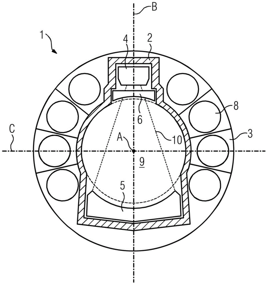
[0021] figure 1 A schematic illustration of a support ring 1 according to the invention of a computed tomography system which is not further illustrated is shown. The support ring 1 has a high-strength frame 2 which is integrated into a lightweight structure 3 , in particular into a braided structure. Various components 8 are provided on the lightweight structure 3 . This part is a rotating accessory or retrofit part, such as cooling elements, electronics boxes, cables, etc. The support ring is hereby rotatable as a whole about an axis of rotation (A) which is arranged perpendicularly to the axes (B) and (C). The high-strength frame 2 and the support ring 1 have a common central opening 9 . The high-strength frame 2 has first, second and third accommodation parts. A radiation source 4 is arranged in the first receptacle. A detector 5 is arranged in the second receptacle. The aperture system 6 is arranged in the third receptacle. The receptacles are realized in such a wa...


PUM


Abstract

The present invention relates to a high-strength frame which has several receptacles for receiving main components of a CT imaging system, wherein each receptacles is formed in at least one direction to at least partially positively receive a main component, a tailor-made arrangement of the main components is realized in the high-strength frame, which provides an exact definition of the beam geometry. Furthermore, the present invention relates to a bearing ring with such a high-strength frame and a computed tomography device with such a bearing ring.

Description

technical field [0001] The invention relates to a high-strength frame for a rotatable support ring of a computed tomography device, a support ring and a computed tomography device with such a high-strength frame. Background technique [0002] A diagnostic method already used in medical technology is computed tomography. In this method, the area to be examined of the patient or object is irradiated in a sheet-like manner and the area to be examined of the patient or object is photographed from different directions. The image reconstruction from the photographs obtained then enables a two-dimensional or three-dimensional representation of the region to be examined and contributes to forming a diagnosis. [0003] Computed tomography devices used for this purpose usually have a gantry consisting of a stationary part and, if necessary, a tiltable part. The gantry is designed as a support structure for the rotating part of the computed tomography apparatus, also called drum. In...

Claims


Application Information

Patent Timeline
IPC IPC(8): A61B6/03
CPCA61B6/035A61B6/06F16C41/00F16C2316/10
Inventor H.吉利策H-J.米勒
Owner SIEMENS HEALTHCARE GMBH
Why Eureka
Try Eureka