
Automatic ring cutting machine

A technology of ring cutting machine and power mechanism, which is applied to automatic/semi-automatic lathes, metal processing machinery parts, turning equipment, etc., can solve the problems of low degree of automation, low production efficiency, increased production cost, etc., and achieves high degree of automation and saving. Production cost, the effect of avoiding work-related injuries

Inactive Publication Date: 2015-04-29
仪征市新城镇三将内燃机配件二厂
View PDF8 Cites 2 Cited by
  • Summary
  • Abstract
  • Description
  • Claims
  • Application Information

AI Technical Summary

Problems solved by technology

[0002] When the piston ring is cast, in order to facilitate demoulding, its thickness gradually changes from one end face to the other end face. In order to facilitate processing, the piston ring needs to be cut into two sections; the existing piston ring cutting is done manually. Put the ring body in the fixture, the fixture rotates with the power mechanism, and then the tool enters the ring for cutting. Generally, one or two equipment requires one worker to operate, and the degree of automation is low; manual operation will also cause waste products in the product. The probability of the increase; manual operation, making the production cost is greatly increased, at the same time, the production efficiency is relatively low

Method used


Image

  • Automatic ring cutting machine
  • Automatic ring cutting machine
  • Automatic ring cutting machine

Examples


Embodiment Construction

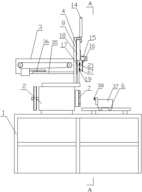
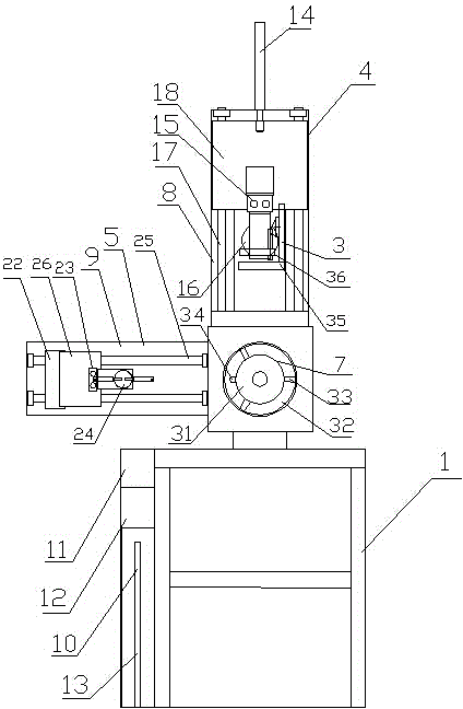
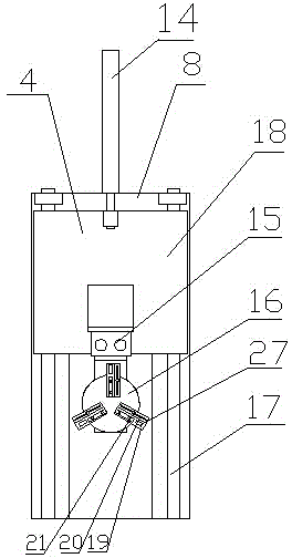
[0020] like figure 1 , 2 , 3, 4, 5, 6, 7, this automatic ring cutting machine includes frame 1, power mechanism 2, feeding mechanism 3, feeding arm 4, unloading arm 5, cutter assembly 6, power mechanism 2. The cutter assembly 6 and the feeding mechanism 3 are respectively fixed on the frame 1, the output end of the power mechanism 2 is fixedly connected to the pneumatic clamp 7, the cutter assembly 6 is arranged corresponding to the pneumatic clamp 7, and the feeding mechanism 3 is arranged in the power mechanism. Above 2, a vertical mounting plate 8 is set above the power mechanism 2, the feeding arm 4 is slidably fixed on the mounting plate 8, the feeding arm 4 slides up and down, and the grab end of the feeding arm 4 slides up to the same position as the The feeding mechanism 3 correspondingly grabs the raw material ring body, and the grab end of the feeding arm 4 slides to the corresponding pneumatic clamp 7 to feed the raw material ring body; a horizontal mounting plate ...


PUM


Abstract

The invention discloses an automatic ring cutting machine, and relates to the field of machinery, in particular to the technical field of manufacture of piston ring cutting devices. The automatic ring cutting machine comprises a frame, a power mechanism, a conveying mechanism, a feeding arm, a discharging arm and a cutter assembly, the power mechanism, the cutter assembly and the conveying mechanism are respectively fixed on the frame, an output end of the power mechanism is fixedly connected with a pneumatic fixture, the cutter assembly corresponds to the pneumatic fixture, the conveying mechanism is arranged above the power mechanism, a vertical mounting plate is arranged above the power mechanism, the feeding arm is slidably fixed on the vertical mounting plate and vertically slides, a horizontal mounting plate is fixedly connected on the side face of the frame, and the discharging arm is slidably fixed on the horizontal mounting plate and horizontally slides. The ring cutting machine is simple in structure and high in automation degree, efficiency and product quality.

Description

technical field [0001] The invention relates to the field of machinery, in particular to the technical field of manufacture of a piston ring cutting device. Background technique [0002] When the piston ring is cast, in order to facilitate demolding, its thickness gradually changes from one end face to the other end face. In order to facilitate processing, the piston ring needs to be cut into two sections; the existing piston ring is cut by manual processing. The ring body is placed in the fixture, the fixture rotates with the power mechanism, and then the cutter enters the ring for cutting. Generally, one or two pieces of equipment need a worker to operate, and the degree of automation is low; manual operation will also cause product waste. The probability of production increases; manual operation greatly increases the production cost, and at the same time, the production efficiency is relatively low. SUMMARY OF THE INVENTION [0003] In order to overcome the above defec...

Claims


Application Information

Patent Timeline
Patent Type & Authority Applications(China)
IPC IPC(8): B23B5/14B23B15/00B23Q3/12B23Q5/40
CPCB23B5/14B23B13/00B23Q3/12B23Q5/40
Inventor 刘后东周华
Owner 仪征市新城镇三将内燃机配件二厂
Learn More