Pipe cutting machine

A technology for cutting machines and pipes, applied in the direction of pipe shearing devices, shearing devices, and accessories of shearing machines, etc., can solve the problems of complex transmission system structure, increased design difficulty, and increased production costs, so as to expand the application range and improve Cutting accuracy and operation stability, space-saving effect

Inactive Publication Date: 2017-02-15
EMERSON PROFESSIONAL TOOLS SHANGHAI
View PDF5 Cites 2 Cited by
  • Summary
  • Abstract
  • Description
  • Claims
  • Application Information

AI Technical Summary

Problems solved by technology

The disadvantage of this structure is that since the motor is arranged longitudinally in the pipe cutting machine, it takes up a lot of space in the longitudinal direction, which limits the scope of application of this cutting machine
In addition, due to the need to use power transmission components that change the direction of 90 degrees, the structure of the transmission system is complicated, which increases the difficulty of design and thus increases the production cost

Method used


Image

  • Pipe cutting machine
  • Pipe cutting machine
  • Pipe cutting machine

Examples


Embodiment Construction

[0019] Hereinafter, exemplary embodiments of the present invention will be described in detail with reference to the accompanying drawings. The description of the exemplary embodiments is for exemplary purposes only, and is by no means a limitation to the present invention and its application or usage.

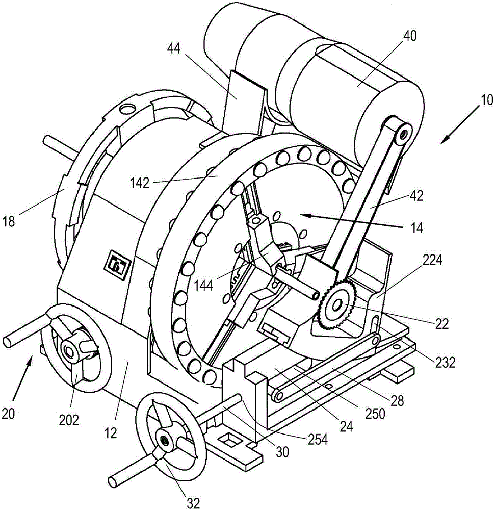
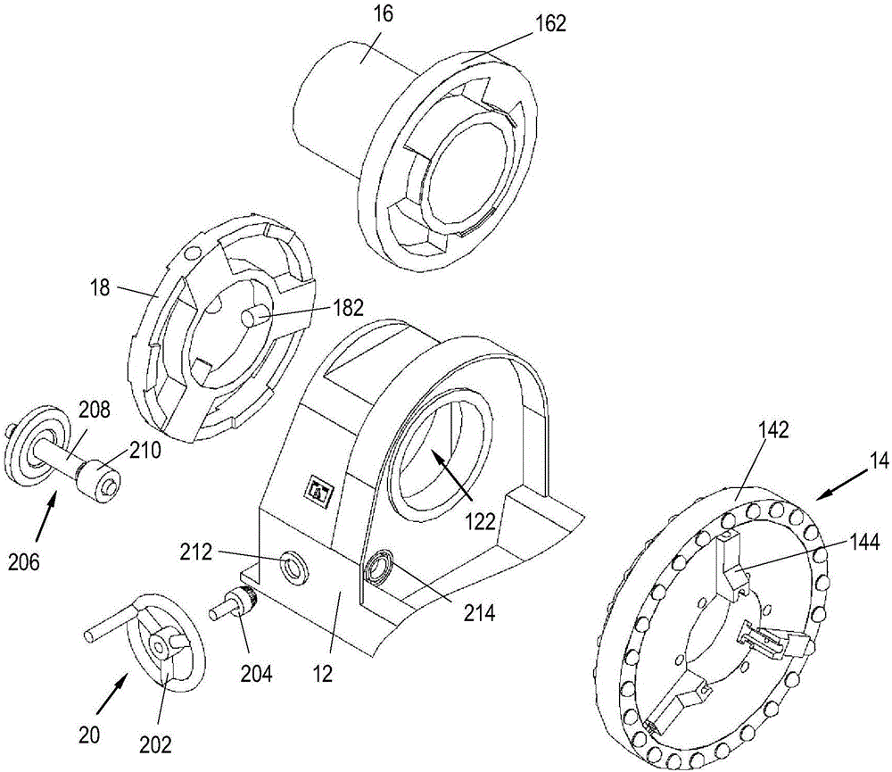
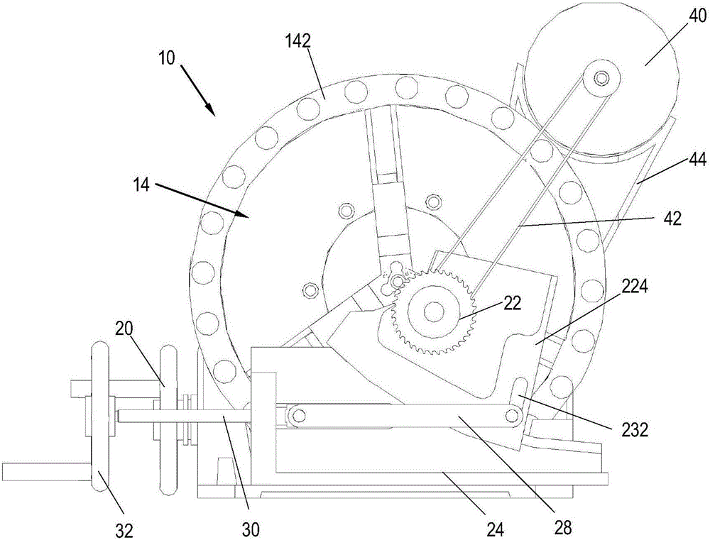
[0020] According to the first embodiment of the present invention, a method such as figure 1 The pipe cutting machine 10 shown. figure 2 An exploded perspective view of the pipe clamping device of the pipe cutting machine 10 according to the present invention is shown. When describing the pipe cutting machine 10 of the present invention with reference to the drawings, the longitudinal direction refers to the direction parallel to the axial direction of the pipe containing hole into which the pipe to be cut is placed, that is, it is positioned in the cutting machine The direction in which the axis of the pipe to be cut is parallel to the direction in which the transverse directio...


PUM


Abstract

The invention relates to a pipe cutting machine. The pipe cutting machine comprises a base, a pipe cutting tool and a motor, wherein the base is provided with a clamping device which is used for clamping a pipe to be cut and can be used for driving the pipe to rotate about the longitudinal axis of the pipe; the pipe cutting tool can move relative to the base; the motor is used for supplying power to the pipe cutting tool; the motor is fixedly arranged on the base; the rotating axis of the motor is parallel to the rotating axis of the pipe cutting tool; the pipe cutting tool can move close to or far away from the pipe to be cut. By adopting the pipe cutting machine disclosed by the invention, the space occupied in the vertical direction can be reduced greatly, so that the application range is enlarged. Moreover, the pipe to be cut is driven to rotate automatically, and the cutting tool does not rotate about the pipe to be cut, so that the operation difficulty of the pipe cutting machine can be lowered, and the use safety is enhanced.

Description

Technical field [0001] The invention relates to a pipe cutting tool, and more specifically, to a pipe cutting machine capable of improving cutting accuracy and having a compact structure. Background technique [0002] At present, most of the cutting operations for pipes, especially stainless steel pipes, are done by grinding wheel saws. Although the cutting speed of the grinding wheel saw is relatively fast, its cutting accuracy is low, the sparks during cutting are large, and the cutting quality is poor. Therefore, the grinding wheel saw can only meet the requirements of pipe cutting with low cutting accuracy, but cannot meet the application of high cutting quality requirements. In addition, this kind of grinding wheel saw requires manual operation by the operator, so its operation process is affected by the subjective factors of the operator, which may further reduce the cutting quality and cutting accuracy. In addition, it may cause injury to the operator during the use of t...

Claims


Application Information

Patent Timeline
Patent Type & Authority Patents(China)
IPC IPC(8): B23D21/00B23D33/02
Inventor 哈拉尔德·克龙多费尔周启吴端
Owner EMERSON PROFESSIONAL TOOLS SHANGHAI
Why Eureka
Try Eureka