Eureka AIR delivers breakthrough ideas for toughest innovation challenges, trusted by R&D personnel around the world.

Material discharging mechanism of core column welding machine

A welding machine and core column technology, applied in welding equipment, auxiliary welding equipment, welding/cutting auxiliary equipment, etc., can solve the problems of unfavorable large-scale production and restriction of production efficiency, achieve compact structure, reduce manpower and material resources, and improve production efficiency effect

Inactive Publication Date: 2015-04-29
江苏金顺光电科技有限公司
View PDF5 Cites 1 Cited by
  • Summary
  • Abstract
  • Description
  • Claims
  • Application Information

AI Technical Summary

Problems solved by technology

Manual cutting is generally used in the automatic welding machine, which has certain limitations in speed, accuracy, safety and efficiency. Due to manual cutting, the improvement of production efficiency is restricted, and it is also not conducive to large-scale production.

Method used


Image

  • Material discharging mechanism of core column welding machine
  • Material discharging mechanism of core column welding machine
  • Material discharging mechanism of core column welding machine

Examples


Embodiment 1

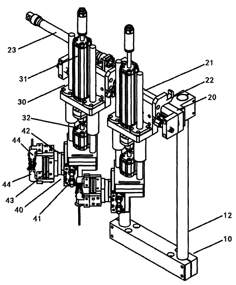
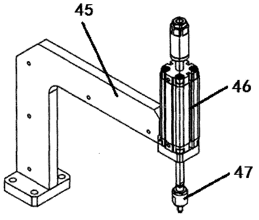
[0018] Such as Figure 1~4 As shown, the unloading mechanism of the stem welding machine described in this embodiment includes a bracket assembly 10, a shifting assembly 20, a lifting assembly 30, a clamping assembly 40 and a PLC controller (not shown in the figure). The displacement assembly 20 is installed on the support assembly 10, and the displacement assembly 20 includes a horizontal guide rail 21 arranged on the vertical support 12 of the support assembly 10, and one or more sliders are installed on the horizontal guide rail 21. seat 22, and a displacement cylinder 23 for driving the slider mounting base 22 to move on the horizontal guide rail; the lifting assembly 30 is installed on the slider mounting base 22, and the lifting assembly 30 includes The first lifting cylinder 31 on the slider mounting base 22, and the second lifting cylinder 32 connected to the lower end of the telescopic rod of the first lifting cylinder 31; the lower end of the telescopic rod of the se...

Embodiment 2

[0020] Since the compression universal head in Embodiment 1 needs to have relatively high hardness, as well as certain toughness and strength, it usually needs to be made of tool steel. In this embodiment, the compression universal head is formed by casting, and its chemical composition is as follows: C: 0.80-0.92wt%, Cr: 1.36-1.55wt%, Mn: 0.42-0.55wt%, Si: 0.10 ~0.15wt%, V: 0.12~0.15wt%, Ti: 0.02~0.03wt%, Ni≤0.20wt%, Cu≤0.20wt%, P≤0.030wt%, S≤0.030wt%, the balance is Fe and Unavoidable impurities; after casting, heat the billet to 980-1020°C for 2-3 hours, then quench it in quenching oil at 120-150°C for 30-35 seconds, and then heat it to 350-380°C for heat preservation After 5-5.5 hours, put it into a sodium nitrate solution with a temperature of 60-80° C. and a concentration of 10 wt % for quenching treatment for 15-20 seconds. The tensile strength of the compacted universal head obtained through the above-mentioned casting and post-treatment can reach 1520-1700 MPa, and t...


PUM

PropertyMeasurementUnit
Tensile strengthaaaaaaaaaa

Abstract

The invention relates to a material discharging mechanism of a core column welding machine. The material discharging mechanism comprises a bracket assembly, wherein a displacement assembly is arranged on the bracket assembly and comprises a horizontal guide rail, slide block mounting seats and a displacement air cylinder are arranged on the horizontal guide rail, a lifting assembly is arranged on each slide block mounting seat and comprises a first lifting air cylinder and a second lifting air cylinder, the lower end of a telescopic rod of each second lifting air cylinder is connected with a clamping assembly, each clamping assembly comprises a rotary seat, a pressing arm, a rotary air cylinder and a clamping air cylinder, each pressing arm is used for pressing a core column, each rotary air cylinder is used for driving the corresponding rotary seat to rotate, each pressing arm comprises a fixing frame, a pressing air cylinder and a pressing universal joint, and each pressing universal joint is arranged at the end part of a telescopic rod of the corresponding pressing air cylinder. The material discharging structure has the advantages that the structure is compact, the firmness and durability are realized, the automatic control is realized, the safety and reliability are realized, the labor and material are saved, and the production efficiency is obviously improved.

Description

technical field [0001] The invention belongs to the technical field of mechanical equipment, in particular, the invention relates to a blanking mechanism of a stem welding machine. Background technique [0002] In the prior art, most manufacturers in the bulb production and processing industry have begun to use automatic electric welding machines to weld the stem to the filament. The automatic welding machine usually includes a worktable, a central turntable located on the worktable, and a vibrating plate, a clamp opener, a rotary feeding mechanism, a positioning mechanism, a detection mechanism, a light foot cutting mechanism, a flattening mechanism, and a spot welding mechanism are arranged around the turntable in turn. institutions and feeding institutions. Manual blanking is generally used in the automatic welding machine, which has certain limitations in speed, accuracy, safety and efficiency. Manual blanking restricts the improvement of production efficiency and is no...

Claims


Application Information

Patent Timeline
IPC IPC(8): B23K37/00
CPCB23K37/00
Inventor 邵维高
Owner 江苏金顺光电科技有限公司
Why Eureka
Eureka Blog
Learn More