Clamping device for ball valve body

A clamping device and valve body technology, applied in auxiliary devices, positioning devices, clamping and other directions, can solve the problems of low working efficiency of the ball valve body, complicated clamping device, increased manufacturing cost, etc., and achieve stable processing and simple structure. , The effect of simple clamping action

Inactive Publication Date: 2015-04-29
TIANJIN YUANDA VALVE CO LTD
View PDF0 Cites 2 Cited by
  • Summary
  • Abstract
  • Description
  • Claims
  • Application Information

AI Technical Summary

Problems solved by technology

When machining the hole on the valve body 10, the peripheral surface of the valve body needs to be clamped and processed, but in the prior art, the clamping device for clamping such a connecting rod head to process the through hole is complicated, so that the connection The processing of the rod head is extremely inconvenient, so the work efficiency of the processing of the ball valve body is low, which increases the manufacturing cost

Method used


Image

  • Clamping device for ball valve body
  • Clamping device for ball valve body
  • Clamping device for ball valve body

Examples


Embodiment Construction

[0013] Next, a clamping device for a ball valve body as an example of the present invention will be described based on the drawings.

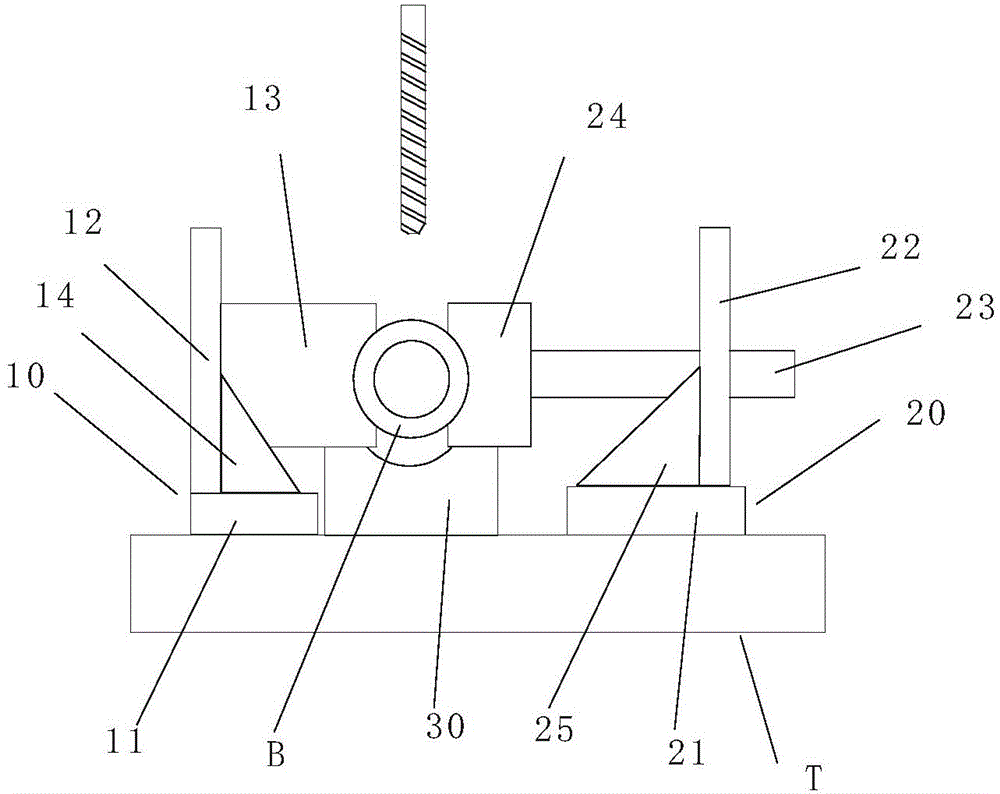
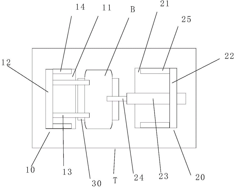
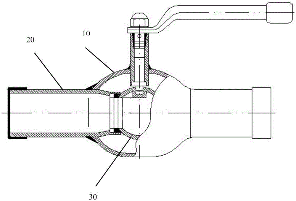
[0014] figure 1 It is a front view showing that the ball valve body is clamped by the clamping device of the present invention. figure 2 It is a plan view showing that the clamping device of the present invention clamps the valve body of the ball valve. image 3 is a sectional view showing a ball valve.

[0015] Such as figure 1 , figure 2 As shown, the clamping device of the ball valve body of the present invention has a first support 10 and a second support 20 installed on the workbench, and the first support 10 has a first bottom plate 11 installed on the workbench T and the first vertical plate 12 erected vertically on the first bottom plate 11, the second support 20 has a second bottom plate 21 installed on the workbench T and a second vertical plate 22 vertically erected on the second bottom plate 21 , the first vertical plate 11 ...


PUM


Abstract

The invention provides a clamping device capable of conveniently clamping a ball valve body. The clamping device is provided with a first support seat and a second support seat which are mounted on a work bench; the first support seat is provided with a first bottom plate mounted on the work bench, and a first vertical plate perpendicularly arranged on the first bottom plate; the second support seat is provided with a second bottom plate mounted on the work bench, and a second vertical plate perpendicularly arranged on the second bottom plate; the first vertical plate and the second vertical plate are oppositely arranged; a pair of crescent first clamping jaws in parallel are perpendicularly arranged on the first vertical plate; the second vertical plate is provided with a connecting shaft in a penetrating manner, and the connecting shaft is connected with a piston of a hydraulic cylinder and can move in a direction perpendicular to the second vertical plate; one end of the connecting shaft is connected with a crescent second clamping jaw; the ball valve body is clamped by virtue of crescent recesses of the pair of first clamping jaws and the crescent recess of the second clamping jaw from two sides.

Description

technical field [0001] The invention relates to a clamping device for a ball valve body. Background technique [0002] The ball valve is connected or disconnected by rotating the ball in the valve body. With the rapid development of science and technology, the production process and product structure of ball valves have been continuously improved, and they have rapidly developed into a major valve category. In my country, ball valves are widely used in petroleum refining, long-distance pipelines, chemical industry, papermaking, pharmaceuticals, water conservancy, electric power, municipal, steel and other industries, and occupy a pivotal position in the national economy. Especially for welded ball valves, the stability of quality and high performance cannot be achieved by ordinary cast steel ball valves. The service life of fully welded ball valves is much longer than that of cast steel ball valves, so they are more widely used. [0003] In the existing technology, such as...

Claims


Application Information

Patent Timeline
Patent Type & Authority Applications(China)
IPC IPC(8): B23K37/04
CPCB23Q3/082B23Q3/062
Inventor 魏成和
Owner TIANJIN YUANDA VALVE CO LTD
Why Eureka
Try Eureka