Supercharge Your Innovation With Domain-Expert AI Agents!

Method for producing hollow articles by fluid-assisted injection

A technology for hollow and finished products, which is applied in the field of fluid-assisted injection molding and the system device for realizing the molding method, which can solve the problems of low, hollow inner wall that will not solidify immediately, high requirements for mold cavity sealing, blockage, etc.

Active Publication Date: 2017-04-19
BEIJING CHN TOP MACHINERY
View PDF4 Cites 0 Cited by
  • Summary
  • Abstract
  • Description
  • Claims
  • Application Information

AI Technical Summary

Problems solved by technology

However, it is also very easy to find shrinkage cavity or shrinkage defects in the resin section of the water-assisted molding hollow product, as well as incomplete filling of the product in the cavity.
This is mainly due to the difference in physical properties between the medium used in gas-assisted molding (generally high-pressure nitrogen) and the medium (water) used in water-assisted injection molding; Due to the low heat capacity of nitrogen, the hollow inner wall does not solidify immediately, but cools from the outer wall of the product in contact with the mold cavity wall to the hollow inner wall. At the same time, due to the compressibility of nitrogen, that is, nitrogen has expansion pressure to push the melt toward the mold. Cavity wall movement supplements the shrinkage and fully fills the cavity. Even after the hollow molding is completed, high-pressure nitrogen pressure holding operation can eliminate defects such as shrinkage and incomplete cavity filling; when water-assisted molding is used, due to the heat conduction of water The heat rate of water is 40 times that of nitrogen, and the heat capacity of water is 4 times that of nitrogen. The inner wall of the hollow body will quickly form a hard solidified layer, and at the same time, the outer wall in contact with the mold cavity wall will also quickly form a hard solidified layer under the cooling of the mold. layer, but water is incompressible, which means that without sufficient resistance during the flow filling process, sufficient water pressure cannot be developed to act on the resin body, which results in a post-cured part between the two hard cured layers. Defects such as shrinkage cavity or shrinkage porosity occur, and the uncured melt cannot be pushed to completely fill the thin-walled structure in the cavity
For the defect that the product is not completely filled in the cavity, it is a good method to fully fill the mold cavity with the screw pressure when the melt fills the cavity; however, when this method is used, the water needle valve At the moment of opening, the melt glue in the cavity is poured into the water needle mechanism, causing the water needle to block and affecting the continuity of production; at the same time, when the switch valve connecting the cavity and the overflow cavity is opened and the water is assisted in the molding, the inside of the cavity The melt pressure relaxes, which cannot completely solve the shrinkage / shrinkage cavity problem in the product wall
On September 19, 2012, in the authorized announcement number published in the Chinese patent literature: CN102672921B "Molding method of thermoplastic resin hollow products", the inventor proposed to use high-pressure gas reverse pressurization in the melt filling process to solve the problem. Problems such as shrinkage porosity or shrinkage cavity in water-assisted molding have good effects, but during the implementation process, it is found that the sealing requirements of the mold cavity are relatively high, and the implementation cost is relatively high. At the same time, this method cannot Solve the problem of water needle blockage

Method used


Image

  • Method for producing hollow articles by fluid-assisted injection
  • Method for producing hollow articles by fluid-assisted injection
  • Method for producing hollow articles by fluid-assisted injection

Examples


Embodiment Construction

[0020] specific implementation plan

[0021] The technical characteristics of the present invention and related technologies thereof are further elaborated below in conjunction with the accompanying drawings through specific implementation schemes:

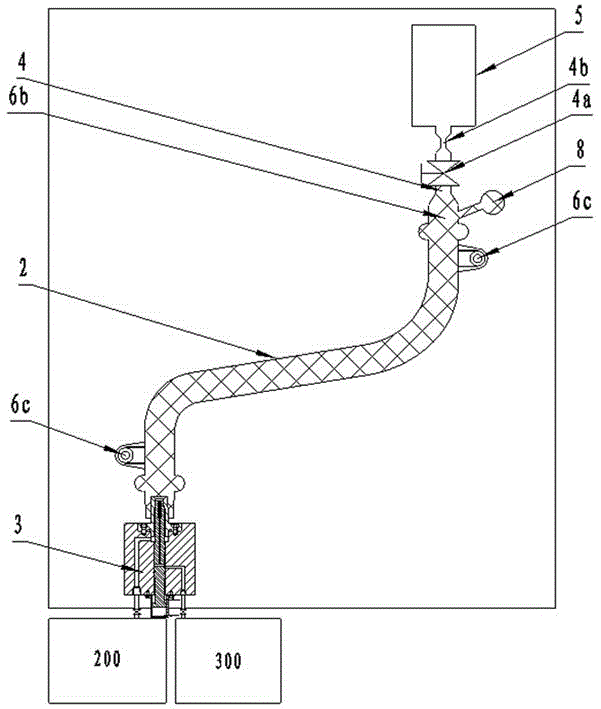
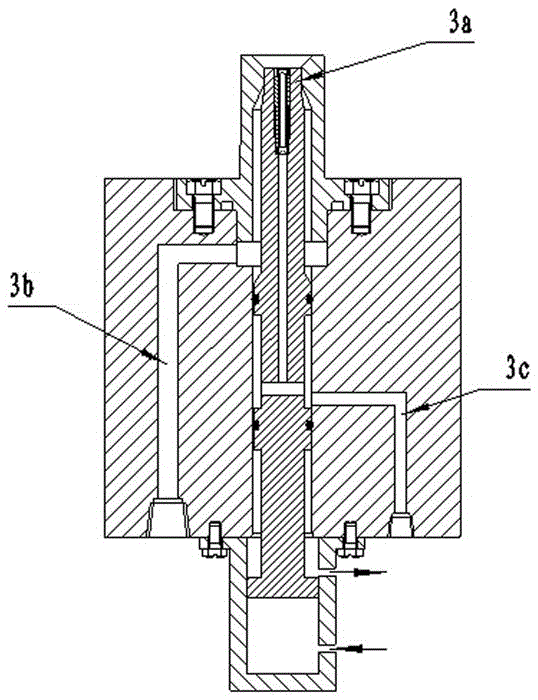
[0022] Such as Figure 1-8 Schematic, the numbers in the figure represent respectively: 100 - injection molding machine, 200 - water injection control device, 300 - high pressure gas injection control device, 1a - moving mold, 1b - fixed mold, 2 - mold cavity, 3 - water needle Device, 3a - Fluid Outlet, 3b - Water Passage, 3c - Gas Passage, 4 - Connecting Channel, 4a - Switching Valve, 4b - Flow Restricting Element, 5 - Spill Chamber, 6 - Hollow Product, 6b - Process Residue , 6c - external fixed connection structure, 7 - water, 8 - gate, 8a - runner system, 9 - injection unit of injection molding machine

[0023] Such as Figure 8 The hollow product 6 shown in this embodiment is a hollow water pipe, the resin material used is ...


PUM

PropertyMeasurementUnit
densityaaaaaaaaaa
diameteraaaaaaaaaa

Abstract

The invention provides a method for producing hollow products by fluid-assisted injection, relates to a method for molding high polymer materials, and in particular relates to a fluid-assisted injection molding method and a system device for realizing the molding method. The invention provides a molding system and the molding method, wherein the molding system mainly consists of an injection molding machine (100), a water flow injection control device (200), a high-pressure gas injection control device (300), an injection molding mould (400), a water needle device (3) and a connecting pipeline; the molding method comprises a processing step of producing the hollow products by the molding system. The method and the system have the advantages that the inner walls of the products are smooth and are much better than those of products molded by the common water-assisted technology; the defect that the thin wall part is not completely filled and the defect of shrinkage cavity, shrinkage porosity, stratification or the like which are caused in the common water-assisted injection molding process are not found; furthermore, the deviation of the pipe inner diameter is within the range of + / -0.3mm and is less than the range of + / -0.5; a sampling test is carried out on all parts, and the strength property and the like are in accordance with the requirements of the products.

Description

technical field [0001] The invention relates to a molding method for polymer materials, in particular to a fluid-assisted injection molding molding method and a system device for realizing the molding method. [0002] technical background [0003] Fluid (water) assisted injection molding technology is a technology that controls fluid (water) and injects it into a specific melting area of ​​the part to form a hollow. After injecting the molten thermoplastic melt, use a water needle to inject water into its core. The front of the water acts on the molten core of the part. From the front of the water to the transition section of the melt, a thin layer of plastic film is solidified, pushing The polymer melt fills the mold cavity to obtain a hollow product. Compared with gas-assisted injection molding technology, fluid (water) assisted injection molding technology has advantages such as shorter cooling time and molding cycle, smoother inner surface of product, more uniform thickn...

Claims


Application Information

Patent Timeline
Patent Type & Authority Patents(China)
IPC IPC(8): B29C45/17B29C45/26
CPCB29C45/0025B29C45/1706B29C2045/1707
Inventor 唐庆华郭金源
Owner BEIJING CHN TOP MACHINERY
Features
  • R&D
  • Intellectual Property
  • Life Sciences
  • Materials
  • Tech Scout
  • Unparalleled Data Quality
  • Higher Quality Content
  • 60% Fewer Hallucinations
Learn More