
Mine vehicle-mounted hydraulic winch

A hydraulic winch, vehicle-mounted technology, applied in hoisting devices, clockwork mechanisms, etc., can solve the problems of inconvenient material or mechanical equipment transportation, inflexible operation methods, and affecting production efficiency, and achieve compact structure and braking effect Good, simple and practical braking effect

Active Publication Date: 2015-04-29
TAIYUAN INST OF CHINA COAL TECH & ENG GROUP +2
View PDF4 Cites 1 Cited by
  • Summary
  • Abstract
  • Description
  • Claims
  • Application Information

AI Technical Summary

Problems solved by technology

[0003] The hydraulic winch has the characteristics of lifting and traction. It is commonly used in ships, ports, construction, mining, metallurgy and other industries. As a mechanical equipment for auxiliary transportation, this kind of winch needs an independent pump station hydraulic system to provide power. Most of them adopt the drum-wound steel wire rope structure, which has simple structure, inflexible operation mode, fixed use location, and inconvenient transportation of materials or mechanical equipment; thirdly, the underground working environment is relatively harsh, and external pollution or impact can easily cause damage to the winch , which affects production efficiency; and the existing winch is generally an open structure with a large volume, which brings a lot of inconvenience to underground use
If it is to be used on vehicles, there is no suitable product in China. Because there are often accelerations or sudden brakes during the transportation of heavy objects on the vehicle, this puts forward very strict requirements on the braking effect of the winch, so that it can withstand more Large shock and vibration, to avoid the danger of winch brake failure

Method used


Image

  • Mine vehicle-mounted hydraulic winch
  • Mine vehicle-mounted hydraulic winch
  • Mine vehicle-mounted hydraulic winch

Examples


Embodiment Construction

[0028] The specific embodiment of the present invention will be further described in conjunction with the accompanying drawings.

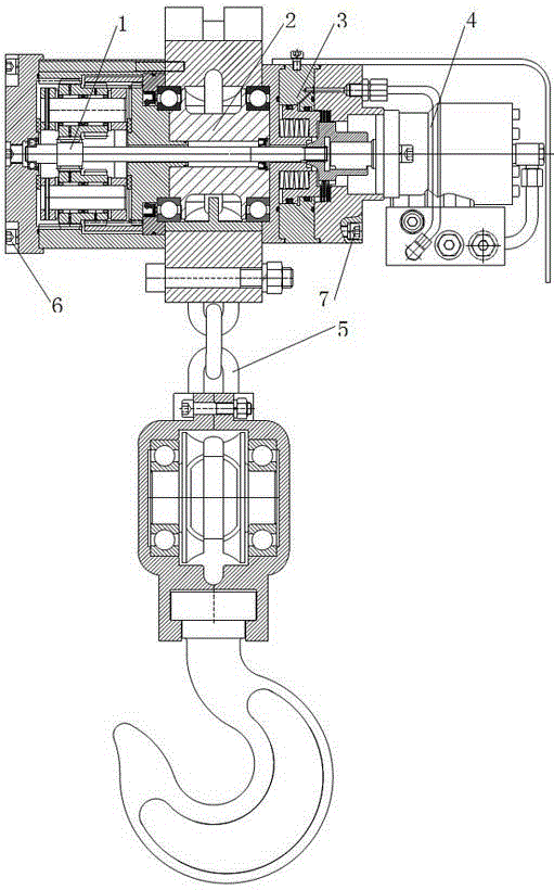
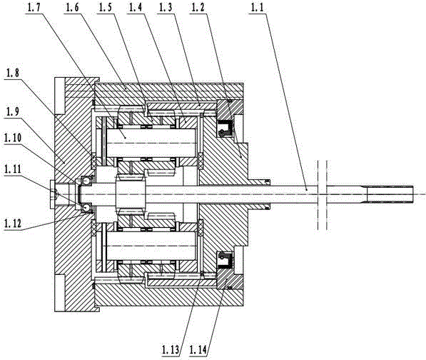
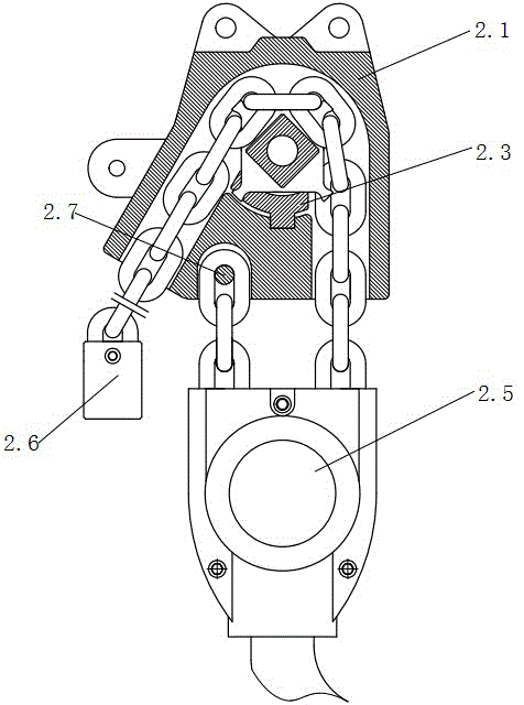
[0029] The main structure of the present invention is composed of a planetary reducer 1, a chain winding mechanism 2, a brake 3, a hydraulic motor assembly 4, a circular chain 5 and the like. The planetary reducer 1 and the winding chain mechanism 2 are axially matched through the bearing end cover 1.14, and are connected through the hexagon socket bolt 6; on the other side, the brake is fixedly connected with the winding chain mechanism 2 through the socket bolt 7; the hydraulic motor assembly 4 is installed On the motor fixing block 3.4, it is fixed by the hexagon socket bolt 4.1; the circular link chain 5 is the carrier of the transmission output, and under the drive of the circular link chain sprocket 2.2, it drives the hook assembly to realize the lifting or putting down of the heavy object.

[0030] The planetary reducer includes a main shaft...


PUM


Abstract

The invention belongs to the technical field of traction equipment, and particularly relates to a mine vehicle-mounted hydraulic winch, which is matched with a mine auxiliary transporting vehicle and aims at solving the problems of the existing hydraulic winch. The mine vehicle-mounted hydraulic winch comprises a planetary speed reducer, a chain mechanism, a brake, a hydraulic motor assembly and a circular chain, wherein the planetary speed reducer, the chain mechanism, the brake and the hydraulic motor assembly are sequentially connected to form a sealed structure, and the brake is provided with disc springs and adopt the multi-disc spring dry brake and counterbalance valve brake double-action type. The mine vehicle-mounted hydraulic winch has the advantages that the mine vehicle-mounted hydraulic winch is especially suitable for auxiliary transporting equipment in coal mine wells; the structure is compact, the traction force is large, the brake is safe and reliable, and the working efficiency is high.

Description

technical field [0001] The invention belongs to the technical field of traction equipment, and in particular relates to a mine vehicle-mounted hydraulic winch used in conjunction with mine auxiliary transport vehicles. Background technique [0002] A hydraulic winch is a winch that uses a hydraulic motor to drive the drum directly or through a gearbox. [0003] The hydraulic winch has the characteristics of lifting and traction. It is commonly used in ships, ports, construction, mining, metallurgy and other industries. As a mechanical equipment for auxiliary transportation, this kind of winch needs an independent pump station hydraulic system to provide power. Most of them adopt the drum-wound steel wire rope structure, which has simple structure, inflexible operation mode, fixed use location, and inconvenient transportation of materials or mechanical equipment; thirdly, the underground working environment is relatively harsh, and external pollution or impact can easily caus...

Claims


Application Information

Patent Timeline
IPC IPC(8): B66D1/08B66D5/14B66D5/26
CPCB66D1/08B66D5/14B66D5/26B66D2700/035
Inventor 薛志勇王希鹏王俊秀李再有黄帅薛亚峰李小军刘妍金雪琪王以超王晓光程俊强龙先江陈明健
Owner TAIYUAN INST OF CHINA COAL TECH & ENG GROUP
Learn More