A kind of submersible thruster

A submersible flow propeller and sewage technology, which is applied in water aeration, water/sewage treatment, chemical instruments and methods, etc., can solve the problems of inconvenient maintenance, sinking in the bottom, and high failure rate, so as to reduce the failure rate and maintain handy effect

Active Publication Date: 2017-01-11
兴港红环保设备河北有限公司
View PDF4 Cites 0 Cited by
  • Summary
  • Abstract
  • Description
  • Claims
  • Application Information

AI Technical Summary

Problems solved by technology

The existing submersible thruster is installed at the bottom of the sewage pool as a whole, and its disadvantages are: 1. The motor and the reducer sink at the bottom of the water, which are easily damaged by water ingress, and the failure rate is high; 2. It can only be used in the condition of no water in the sewage pool It can be installed or disassembled only when it is lowered, and maintenance is very inconvenient

Method used


Image

  • A kind of submersible thruster
  • A kind of submersible thruster
  • A kind of submersible thruster

Examples


Embodiment 1

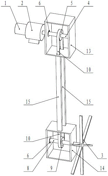
[0025] figure 1 It is a schematic diagram of its structure. In order to facilitate the display of the internal structure of the upper box and the lower box, the front panels of the upper box and the lower box are removed in the figure, which does not mean that it is a non-airtight structure. Such as figure 1 As shown, a submersible pusher includes a motor 1, a reducer 2 and a pusher blade 3, and both the motor 1 and the reducer 2 are set above the water surface of the sewage pool; the motor 1 is connected to the reducer 2, and the reducer 2 is connected to The first horizontal shaft 4, the first sprocket 5 is fixedly arranged on the first horizontal shaft 4, the second horizontal shaft 8 is arranged below the first horizontal shaft 4, the second sprocket 9 is fixedly arranged on the second horizontal shaft 8, and the second sprocket 9 is fixedly arranged on the second horizontal shaft 8. The first sprocket 5 and the second sprocket 9 are connected by a chain 10; the first spr...

Embodiment 2

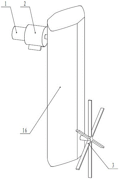
[0031] Such as figure 2 As shown, the difference between embodiment two and embodiment one is:

[0032] The sealing device is an integral case 16 that seals the first sprocket 5, the second sprocket 9 and the chain 10; the first horizontal shaft 4 and the second horizontal shaft 8 are connected to the integral case through the bearing 6 Body 16 is connected.

[0033] The front and rear sides of the integral box body 16 are arranged in a streamlined shape bulging outward.

[0034] The front and rear sides of the integral box 16 are arranged in a shape that bulges outward, so that the water resistance in the left and right directions is increased, so that it is easier to overcome the reaction force caused by the push flow blade 3 when it is working. Enhance the stability of the submersible flowmaker in the sewage tank.

Embodiment 3

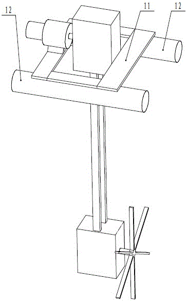
[0036] Such as image 3 As shown, the difference between embodiment three and embodiment one is:

[0037] The submersible flowmaker is fixedly connected to a frame 11 through the foot of the reducer 2 and the upper box 13, the frame 11 is fixedly arranged on two buoys 12, and the buoys 12 float on the water surface of the sewage pool.

[0038] Setting the submersible flowmaker on the two buoys 12 is not only convenient to flexibly set its position in the sewage tank according to the actual situation, but also facilitates automatic adjustment of the working state during its work to ensure its smooth operation.


PUM


Abstract

The invention discloses a novel submersible water impeller. A motor and a speed reducer are arranged above the water level of a sewage basin; the motor is connected with the speed reducer which is connected with a first horizontal shaft; a first chain wheel is fixedly arranged on the first horizontal shaft; a second horizontal shaft is arranged below the first horizontal shaft; a second chain wheel is fixedly arranged on the second horizontal shaft; the first and second chain wheels are connected by virtue of a chain; the first and second chain wheels and the chain are isolated from sewage by using a sealing device; the first and second horizontal shafts are connected with the sealing device through a bearing; the right end of the second horizontal shaft extends out of the sealing device and is fixedly provided with a propelling blade for propelling sewage in the lower part of the sewage basin to flow; the motor and the speed reducer are arranged above the water level of the sewage basin, so that the failure rate is effectively reduced; moreover, the propelling blade is suspended in the sewage basin through the sealing device, so that the novel submersible water impeller can be mounted and disassembled under the condition that water exists in the sewage basin, and the novel submersible water impeller is convenient to maintain.

Description

technical field [0001] The invention relates to a flow pushing device in a sewage treatment system, in particular to a submersible flow pushing device. Background technique [0002] The submersible thruster in the sewage treatment system is used at the bottom of the sewage pool, which includes a motor, a reducer and a push-flow blade; the motor drives the push-flow blade to rotate through the reducer, pushing the sewage at the bottom of the sewage pool to flow, so that the bottom of the pool The sludge also flows with the sewage to prevent the deposition of sludge at the bottom of the pool. The existing submersible thruster is installed at the bottom of the sewage pool as a whole, and its disadvantages are: 1. The motor and the reducer sink at the bottom of the water, which are easily damaged by water ingress, and the failure rate is high; 2. It can only be used in the condition of no water in the sewage pool It can be installed or disassembled only when it is lowered, and ...

Claims


Application Information

Patent Timeline
Patent Type & Authority Patents(China)
IPC IPC(8): C02F3/00C02F3/12C02F1/00C02F7/00B01F15/00
CPCY02W10/10
Inventor 胡海平
Owner 兴港红环保设备河北有限公司
Why Eureka
Try Eureka