Plasma drilling bit

A drilling bit and plasma technology, applied in the direction of drill bits, drilling equipment, earthwork drilling and production, etc., can solve technical problems that cannot be solved, and achieve the effect of increasing mechanical penetration rate, low cost and high efficiency

Active Publication Date: 2015-04-29
CHINA PETROCHEMICAL CORP +1
View PDF3 Cites 23 Cited by
  • Summary
  • Abstract
  • Description
  • Claims
  • Application Information

AI Technical Summary

Problems solved by technology

In order to further increase the ROP and reduce the construction cost, in recent years, foreign universities, oil companies and drilling scientists are exploring new thermal drilling methods such as laser drilling and electric spark drilling to break rocks, but there are still many technical problems. not resolved

Method used


Image

  • Plasma drilling bit
  • Plasma drilling bit
  • Plasma drilling bit

Examples


Embodiment 1

[0029] A plasma drilling bit, in which an axially penetrating fluid channel and an electrode through hole are preset in the drill body, a high-voltage positive electrode and an insulator are fixed in the electrode through hole, a cup-shaped ground electrode is fixed in the bottom of the drill body, and the bottom of the high-voltage positive electrode is For the high-voltage disk electrode, an annular inter-electrode gap is reserved between the high-voltage disk electrode and the cup-shaped ground electrode.

[0030] This embodiment gives the basic technical route. After satisfying the basic conditions such as having a fluid channel, a high-voltage positive electrode and a cup-shaped ground electrode, the plasma drilling work can be completed by cooperating with ground equipment.

Embodiment 2

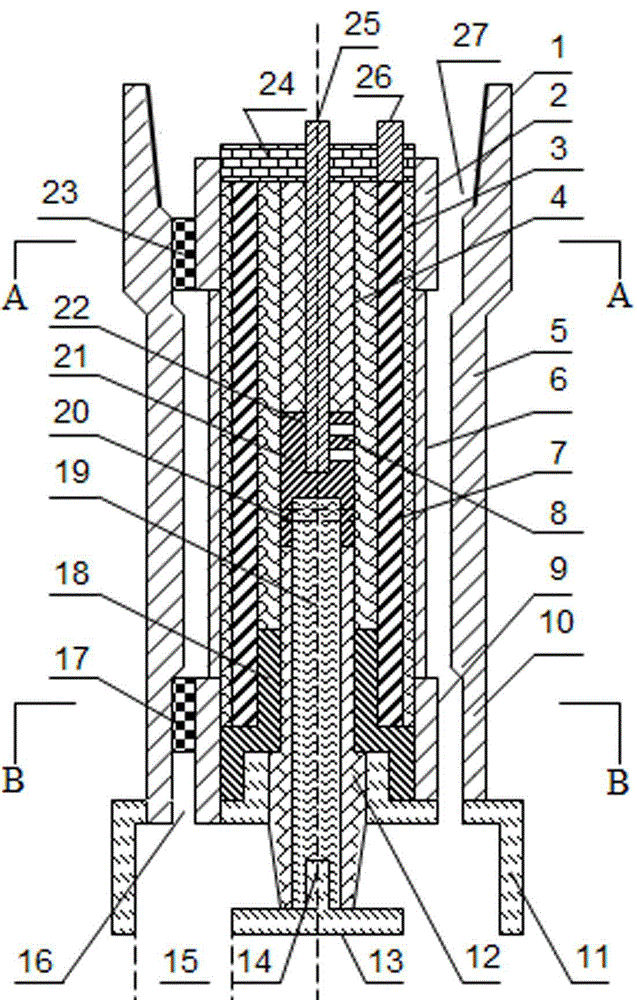
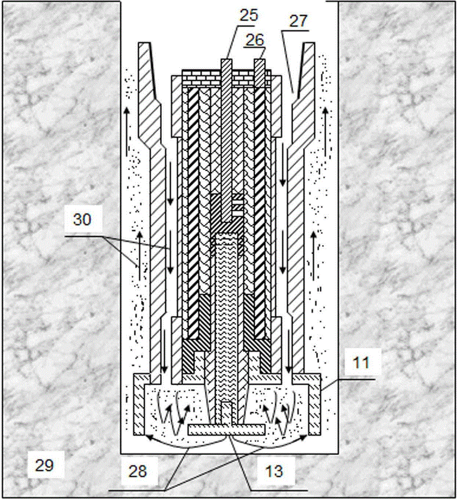
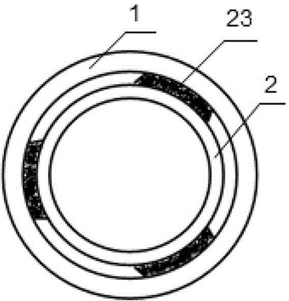
[0032] Refer to the attached figure 1 , figure 2 with image 3 , a plasma drilling drill bit, comprising an outer pipe upper joint 1, an outer pipe body 5, an outer pipe lower joint 10, an inner pipe upper joint 2, an inner pipe body 6, an inner pipe lower joint 9, an upper righting block 23, and a lower righting block 17. High-voltage plate-mounted electrode 13, cup-shaped ground electrode 11, high-voltage handle 19, conductive sleeve 18, connector 21, metal tube 7, pressure cap 24, cable core 25, 26, insulator 3, 4, 12.

[0033]The upper joint 1 of the outer pipe, the body 5 of the outer pipe and the lower joint 10 of the outer pipe are sequentially friction-butt welded to form the outer pipe; The outside of the upper pipe joint 2 and the lower joint 9 are arranged with 3 centralizing blocks 23, 17 along the circumference at intervals of 120°; The outer side of the lower joint 9 of the inner pipe and the lower centralizing block 17 are all provided with threaded steps an...


PUM


Abstract

The invention relates to a plasma drilling bit in the field of drilling bit tools. The technical scheme adopted by the invention is that a fluid passageway and an electrode through hole which respectively and axially communicated are preformed in a bit body; a high-voltage positive electrode and insulators are fixedly connected with the interior of the electrode through hole; the bottom part of the bit body is fixedly connected with an annular ground electrode; the bottom part of the high-voltage positive electrode is provided with a high-voltage panel mounting electrode; an annular interelectrode gap is reserved between the high-voltage panel mounting electrode and the annular ground electrode. The bit penetrates a plasma channel formed in front of to-be-drilled rock under the high-voltage pulse liquid phase microdischarge action to crush the rock, and does not need to be contacted with the surface of the rock, and mechanical lapping is not needed. The plasma drilling bit disclosed by the invention has the advantages that the abrasion of the bit can be reduced, the rate of penetration is increased, and the required energy is low; compared with the conventional mechanical rotary bit, the plasma drilling bit is low in cost and high in efficiency, and can also be applied to industry of mining and the like.

Description

technical field [0001] The invention relates to the field of oil and gas drilling tools, in particular to a plasma drilling bit. Background technique [0002] Over the years, mechanical rotary drilling technology has played a huge role in the rapid development of the global drilling industry. In recent years, with the intensification of drilling efforts in deep wells, ultra-deep wells and geothermal wells, conventional mechanical rotary drilling technology is no longer a “cure-all” technology. Wellbore instability problems such as slow speed, jammed blowout and lost circulation are prominent, which seriously affect the failure of drilling, and consume a lot of energy, and the release of carbon dioxide and other gases seriously pollutes the environment. [0003] Since high-pressure jet drilling began to be popularized and applied in the 1960s, the combined rock breaking method of mechanical rock breaking + hydraulic assisted rock breaking has occupied an absolute dominant po...

Claims


Application Information

Patent Timeline
Patent Type & Authority Applications(China)
IPC IPC(8): E21B10/00
CPCE21B10/00
Inventor 郭先敏蔡西茂杨利杨宁宁曲刚候芳张林伟
Owner CHINA PETROCHEMICAL CORP
Why Eureka
Try Eureka