
Petroleum drilling top drive safety valve protecting joint

A technology for oil drilling and safety valves, which is applied to drilling equipment, drill pipes, drill pipes, etc. It can solve the problems of increasing safety hazards in drilling operations, inability to place filter cartridges, and impacts on drilling operations, so as to reduce drilling risks, operation and use. Convenience and long-lasting effect

Active Publication Date: 2015-04-29
东营市创元石油机械制造有限公司
View PDF9 Cites 2 Cited by
  • Summary
  • Abstract
  • Description
  • Claims
  • Application Information

AI Technical Summary

Problems solved by technology

[0003] The mud is required to be filtered during the drilling process. The general drilling fluid filter device is placed at the root of the internal thread of the drill pipe and supported in the drill pipe by the chamfer inside the drill pipe. The gap is large and each time the drill is tripped, it needs to be taken out and placed manually. , the filtering effect is poor, the work efficiency is low, and the filter cartridge cannot be placed for the high torsion-resistant double-step drill pipe buckle. In order to filter the mud, a filter joint is often added between the lower part of the safety joint and the drill pipe, which is inconvenient to operate and use. Production efficiency low, and increases the safety hazards of drilling operations, which has a great impact on drilling operations

Method used


Image

  • Petroleum drilling top drive safety valve protecting joint
  • Petroleum drilling top drive safety valve protecting joint

Examples


Embodiment Construction

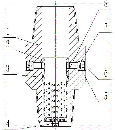
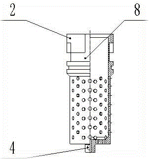
[0018] Now combined with the accompanying drawings of the manual figure 1 , figure 2 The present invention is further described.

[0019] The protection joint of the top drive safety valve for oil drilling includes the main body of the protection joint 1, the filter cartridge 2, the seal 1 3, the disassembly hole 4, the screw 5, the retaining ring 6, the seal 2 7, the reverse L-shaped groove 8, and the protection joint The main body 1 is in the shape of a round tube, with threads processed at both ends. The inner hole has a section with a small inner diameter in the middle part, and there are two symmetrical threaded holes radially upward at this section with a small inner diameter. The outside of the threaded hole is a counterbore , The outer part of the counterbore is processed with an annular groove. The filter cartridge 2 is a cylinder with one end closed. The upper part has a larger diameter. Two symmetrical reverse L-shaped grooves 8 are processed on the upper part of...


PUM


Abstract

Disclosed is a petroleum drilling top drive safety valve protecting joint. According to the petroleum drilling top drive safety valve protecting joint, a joint body is in a round tube shape, and both ends of the joint body are provided with threads; the middle of an internal hole is provided with a small-diameter section, which is radially upwards provided with two symmetric threaded holes, and screws are mounted inside the threaded holes; the inside of the joint body is provided with a filter tube, the upper outer circumferential surface of the filter tube is provided with two symmetric inverted L-shaped grooves matched with the cylindrical sections at the tail ends of the screws to form a rotary positioning structure; the lower outer surface of each inverted L-shaped groove is provided with a ring groove, a sealing member is arranged inside the ring groove and matched with the small-diameter section of the internal hole. The petroleum drilling top drive safety valve protecting joint is of an integrated structure, and the filter tube is directly mounted inside the protecting joint, so that the petroleum drilling top drive safety valve protecting joint is simple and compact in structure, high in reliability, convenient to operate and use and long in service. By applying the petroleum drilling top drive safety valve protecting joint, a filter joint for filtering slurry between the lower portion of a safety joint and a drill pipe can be saved, the slurry quality can be improved, the service life of a top drive safety valve can be prolonged, and the drilling risk and the production cost can be reduced.

Description

technical field [0001] The invention relates to the technical field of drilling in the petroleum industry, in particular to a top drive safety valve protection joint for petroleum drilling. Background technique [0002] At present, the top drive drilling system in oil drilling has been widely used due to its advantages of high efficiency, time-saving column drilling, low risk of continuous rotation and circulation, good for well control, and high safety. The safety joint in the system is located between the lower end of the top drive lower safety valve and the upper end of the drill pipe, and is connected by threads. The safety joint is a safety protection joint in the drill string circulation system and is an important auxiliary drill for protecting the top drive safety valve. Tool. [0003] During the drilling process, it is required to filter the mud. Generally, the drilling fluid filter device is placed at the root of the internal thread of the drill pipe and supp...

Claims


Application Information

Patent Timeline
Patent Type & Authority Applications(China)
IPC IPC(8): E21B17/02E21B21/00
CPCE21B17/02E21B21/106
Inventor 朱怀军李光泉吴天乾王爱宽田相录
Owner 东营市创元石油机械制造有限公司
Learn More