Well structure and method for underground modified mining of heavy oil and super heavy oil reservoir

A technology of super-heavy oil and wellbore structure, applied in chemical instruments and methods, production of fluids, earth-moving drilling, etc., can solve the problems of steam channeling, it is difficult for gas to carry solid-phase catalysts, and the scope of oil reservoirs is limited, etc. achieve the effect of ensuring liquidity

Active Publication Date: 2015-04-29
PETROCHINA CO LTD
View PDF8 Cites 20 Cited by
  • Summary
  • Abstract
  • Description
  • Claims
  • Application Information

AI Technical Summary

Problems solved by technology

Among them, the limitation of steam huff and puff is that its heating radius is limited, only within 30-40 meters, and the recovery factor is low, less than 30% on average; SAGD technology is only suitable for heavy oil reservoirs with a continuous thickness of oil layers greater than 15 meters, and in heterogeneous oil Central Tibet is still facing problems such as serious steam escape and poor economic efficiency
[0005] During the process of steam injection, hydrothermal cracking of heavy oil occurs, but limited by the temperature, the effect of steam injection technology on heavy oil upgrading is limited. The produced heavy oil has high viscosity and low grade, and it needs to be catalyzed by the ground refinery. cracking treatment
[0006] Electric heating technology can quickly heat up the reservoir to over 300°C, and can also realize in-situ upgrading of heavy oil, but the range of heated reservoirs is limited, and can only heat the range of 10 meters near the wellbore, so denser wells need to be deployed network, poor economic efficiency
[0007] The Chinese patent application with the application number 201210587241.1 discloses "A Method for Underground Petroleum Underground Medium and Low Temperature Controlled Catalytic Oxidation and Upgrading Exploitation", which points out that the burning oil layer has the following disadvantages: 1. The progress of the system reaction and the heat generated are determined by the oxygen concentration. It is impossible to achieve more accurate control; 2. The temperature of the system is too high, often reaching above 600°C in oil field applications, but in fact, the fluidity of heavy oil can be greatly improved when it is below 200°C, and the pyrolysis is mostly below 500°C. Can happen, too high grade of heat will inevitably consume more fuel and affect recovery; 3. Coking phenomenon is obvious, forming a wide coking zone in the high temperature area near the front of the combustion front, which not only affects the advancement of the combustion front And the heat transfer process of the system also caused a certain degree of damage to the reservoir
[0010] The above-mentioned prior art has the following problems: 1. The injection technology strategy of the heat-generating catalyst and the reforming catalyst is not provided
Catalysts are solid phase fine particles, which are difficult to distribute evenly in the injection of oxygen-containing gas. In the absence of a carrier solution with good performance, it is difficult for the gas to carry the solid phase catalyst into the oil layer; 2. How to achieve full contact between the catalyst and the oil layer The technical path is not clear
Under the condition of high-speed gas flow injection, a small part of the solid-phase catalyst will enter the oil layer along the large pores or high-permeability strips, but only limited to the large pores and high-permeability strips, and it is difficult for the catalyst to enter the deep part of the oil layer evenly, especially for low permeability Large-scale catalytic upgrading is realized in the region, and the upgrading effect is very limited; 3. The replacement problem after the catalyst fails

Method used


Image

  • Well structure and method for underground modified mining of heavy oil and super heavy oil reservoir

Examples


Embodiment 1

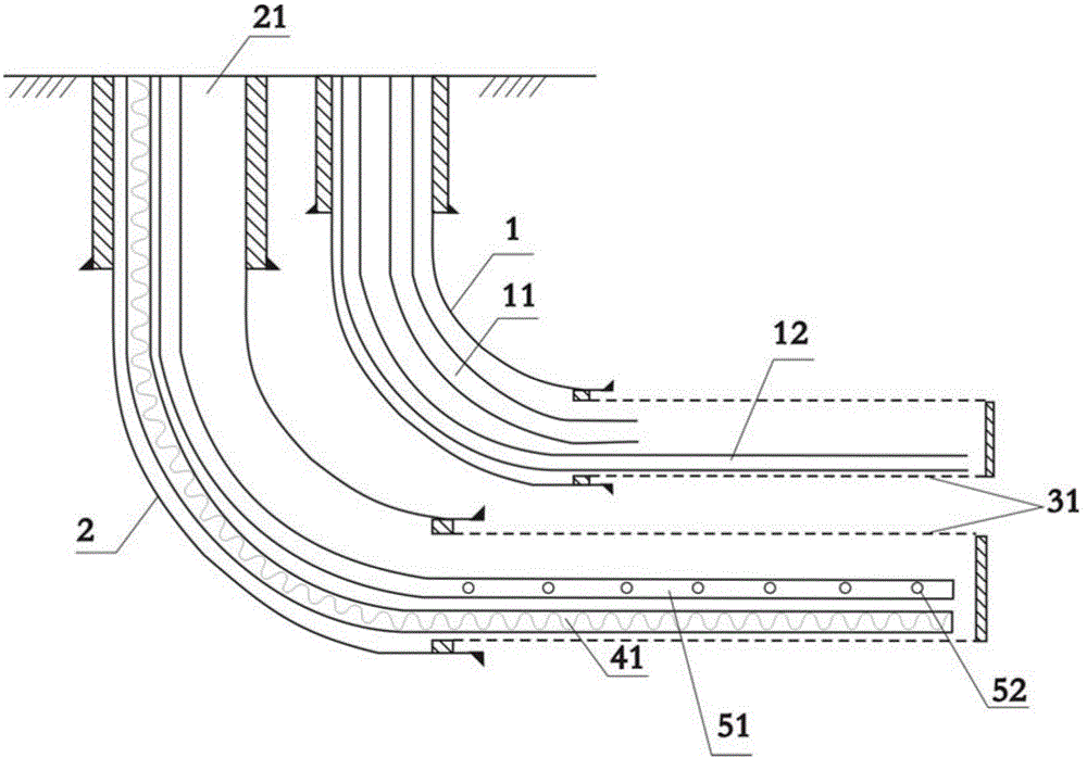
[0060] This embodiment provides a well body structure for underground upgrading and exploitation of heavy oil and super heavy oil reservoirs. The structure of the well body structure is as follows figure 1 As shown, the details are as follows:

[0061] Injection-production well pattern (horizontal well-horizontal well SAGD well pattern) vertical overlap of injection well 1 and production well 2, the horizontal section is parallel to each other, the vertical distance between the horizontal section of injection well and the horizontal section of production well is 5 meters, the horizontal section The length is 500 meters; the injection well 1 is completed through a screen 31 with a nozzle diameter of 9 inches; the production well 2 is completed through a screen 31 with a nozzle diameter of 9 inches;

[0062] The injection well 1 of the injection-production well pattern is provided with parallel double oil pipes stretching into the heel and toe of the horizontal section of the in...

Embodiment 2

[0077] This embodiment provides a well body structure for underground upgrading and exploitation of heavy oil and super heavy oil reservoirs. The structure of the well body structure is as follows:

[0078] The injection-production well pattern is a horizontal well-horizontal well SAGD well pattern, the vertical overlap of the injection well and the production well, the horizontal sections are parallel to each other, the vertical distance of the vertical horizontal section is 5 meters, and the length of the horizontal section is 600 meters; the diameter of the injection well through the nozzle Completion wells with 11-inch screens; production wells completed with 11-inch nozzle diameter screens;

[0079] The injection wells of the injection-production well pattern are provided with parallel double oil pipes extending into the heel and toe of the horizontal section of the injection well. into the heel), the nozzle diameter of the long tubing is 4.5 inches, and the nozzle diamet...

Embodiment 3

[0094] This embodiment provides a well body structure for underground upgrading and exploitation of heavy oil and super heavy oil reservoirs. The structure of the well body structure is as follows:

[0095] The injection-production well pattern is a horizontal well-horizontal well SAGD well pattern, the vertical overlap of the injection well and the production well, the horizontal sections are parallel to each other, the vertical distance of the vertical horizontal section is 5 meters, and the length of the horizontal section is 700 meters; the diameter of the injection well through the nozzle Completion wells with 11-inch screens; production wells completed with 11-inch nozzle diameter screens;

[0096] The injection wells of the injection-production well pattern are provided with parallel double oil pipes extending into the heel and toe of the horizontal section of the injection well. into the heel), the nozzle diameter of the long tubing is 4.5 inches, and the nozzle diamet...


PUM

PropertyMeasurementUnit
diameteraaaaaaaaaa
diameteraaaaaaaaaa
particle diameteraaaaaaaaaa

Abstract

The invention provides a well structure and a method for underground modified mining of a heavy oil and super heavy oil reservoir. The well structure comprises oil tubes, a catalyst injection tube and a heating device; injection holes unevenly distributed are formed in the horizontal section of the catalyst injection tube; the heating device comprises a high-energy fused salt heating tube, an electric heating tube, an electric resistance wire heating device, an electromagnetic heating device, a radio-frequency heating device or a microwave heating device; the oil tubes comprise parallel dual oil tubes, concentric dual oil tubes or single continuous punched oil tubes; the invention also provides the method for performing the modified mining on the heavy oil reservoir by utilizing the well structure. According to the well structure and the method for the underground modified mining of the heavy oil and super heavy oil reservoir, provided by the invention, oil can be rapidly dissolved and the viscosity of crude oil is greatly reduced, so the fluidity of mined fluid is further increased, and long-time continuous modification of the oil reservoir can be realized.

Description

technical field [0001] The invention relates to a well body structure and a method for exploiting heavy oil reservoirs in an oil field, in particular to a well body structure and a method for underground catalytic upgrading and exploitation of heavy oil-based ultra-heavy oil reservoirs, and belongs to the technical field of petroleum exploitation. Background technique [0002] Due to the high viscosity of crude oil (underground viscosity greater than 100mPa·s) and high flow resistance, heavy oil is difficult to recover by cold recovery techniques such as conventional water flooding. [0003] Because the viscosity of heavy oil is sensitive to temperature, the viscosity of heavy oil can be greatly reduced and its flow capacity can be improved after heating up. Therefore, thermal recovery technologies such as steam injection, electric heating, and fire are widely used at home and abroad to recover heavy oil. [0004] Heavy oil steam injection recovery technologies mainly includ...

Claims


Application Information

Patent Timeline
Patent Type & Authority Applications(China)
IPC IPC(8): E21B43/16E21B43/22E21B43/24E21B43/30C09K8/58
CPCC09K8/58E21B43/16E21B43/24E21B43/30
Inventor 吴永彬王红庄刘尚奇张艳娜
Owner PETROCHINA CO LTD
Why Eureka
Try Eureka