The Method of Automatically Eliminating Backlash of Angle-Limited Gears

A technology of gear teeth and side clearance, applied in the direction of belt/chain/gear, transmission device parts, mechanical equipment, etc., can solve the research on the dynamic characteristics of electromechanical systems, can not meet the needs of anti-backlash gear mechanism, unfavorable space utilization and assembly realization and other issues, to achieve the effect of reducing processing costs and materials, compact structure, and reducing volume

Inactive Publication Date: 2017-11-28
SOUTH WEST INST OF TECHN PHYSICS
View PDF6 Cites 0 Cited by
  • Summary
  • Abstract
  • Description
  • Claims
  • Application Information

AI Technical Summary

Problems solved by technology

At the same time, in order to ensure that the backlash can be better eliminated at any angle within the range of 360°, generally 2 to 4 sets of springs are installed along the circumferential direction on the main and loading pinion gear surfaces to provide forced tension for eliminating backlash. The number of springs is large, the structure is complex, and the size is large
[0008] In more industrial control and measurement applications, the control object or the measured object often only needs to rotate reciprocally within a small limited range, and most of the tooth surfaces of the main and loading pinions fixed on it are in the rotating position. Outside the range, they never participate in meshing, which wastes processing and material costs. In some products with limited mechanism space, these teeth are not only useless at all, but also occupy a large space and easily interfere with surrounding components. Conducive to space utilization and assembly realization, limiting the application of the mechanism
With the increasing complexity of the working conditions of anti-backlash gears, the existing anti-backlash gears cannot meet the needs of research on the dynamic characteristics of electromechanical systems with anti-backlash gear mechanisms.

Method used


Image

  • The Method of Automatically Eliminating Backlash of Angle-Limited Gears
  • The Method of Automatically Eliminating Backlash of Angle-Limited Gears
  • The Method of Automatically Eliminating Backlash of Angle-Limited Gears

Examples


Embodiment Construction

[0018] In order to make the purpose, technical solutions and advantages of the embodiments of the present invention clearer, the embodiments of the present invention will be further described in detail below in conjunction with the embodiments and the accompanying drawings. Here, the exemplary embodiments of the present invention and their descriptions are only used to explain the present invention, but not to limit the present invention.

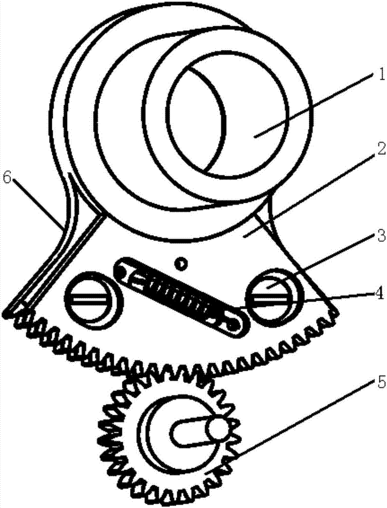
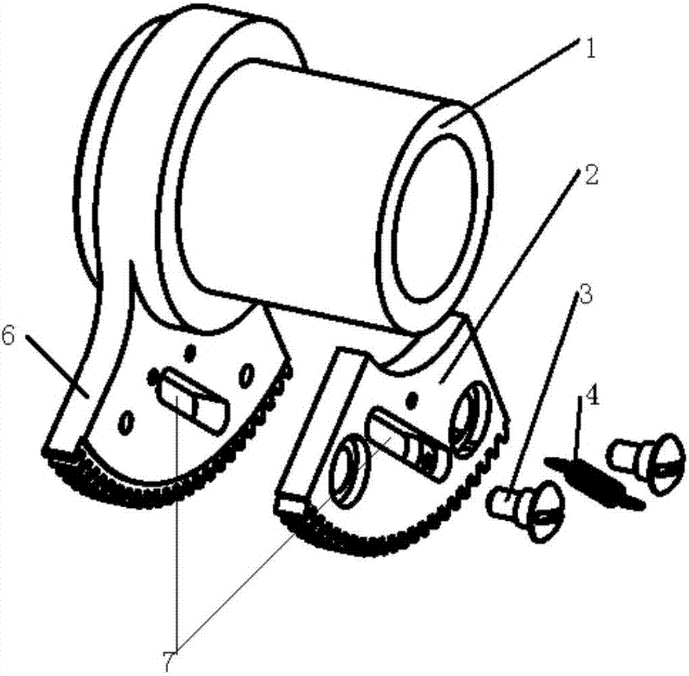
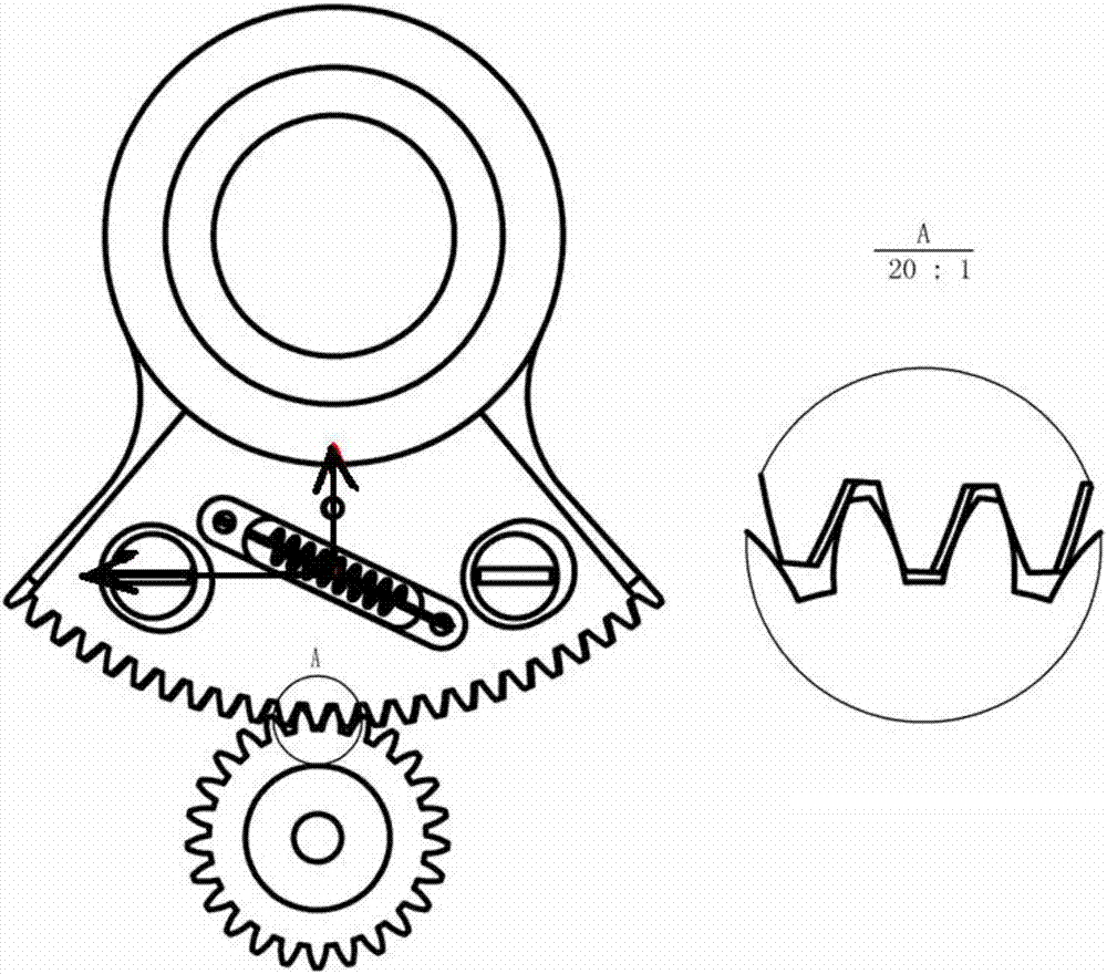
[0019] refer to figure 1 , figure 2. A pair of gears with fixed rotation axis and meshing with each other are driving gear and driven gear 5 respectively. Among them, the driving gear is composed of two pieces, the gears have the same shape, and the effective working parts are all fan-shaped. The main tooth and auxiliary tooth of driving gear all can adopt straight-toothed cylindrical tooth, and driven gear 5 is the same. The radius of the cylindrical surface at the bottom of the auxiliary tooth is the same as that of the cylindrical s...


PUM


Abstract

The invention discloses a method for automatically eliminating limited angle gear backlash, and aims to provide a compact limited angle gear backlash eliminating mechanism which is simple and compact in structure and capable of realizing gear transmission without backlash, improving gear transmission precision, reducing cost and improving assembling capacity. The technical scheme for implementing the method includes that one of a driving gear and a driven gear which are engaged with each other is divided into a main sector gear and an auxiliary sector gear, a fixed main gear working portion and the loaded auxiliary gear are sectored, a bottom arc of a small end sector of the loaded auxiliary gear fits with a cylindrical surface of a gear rotating shaft cylinder, inclined hole grooves (7) are formed in sectors of the fixed main gear and the loaded auxiliary gear, and gear tension springs (4) keeping a tension state are mounted in the inclined hole grooves, the fixed main gear and the loaded auxiliary gear are connected together by loading the sector of the auxiliary gear through the gear tension springs, and the fixed main gear and the loaded auxiliary gear are mutually staggered to form a certain circumference angle and engaged with the driven gear in opposite directions.

Description

technical field [0001] The invention relates to a method for automatically eliminating backlash on the tooth side of a limited-rotation-angle gear, which is suitable for backlash-free gear transmission with limited rotation angles in a limited volume space. Background technique [0002] Gear transmission is a main transmission method widely used in various mechanical systems and equipment. Gear transmission mechanism is a common control and measurement mechanism in electromechanical products. The accuracy of gear transmission directly affects the control and measurement performance of the product. When the gear transmission mechanism is in one-way transmission, the transmission precision is high. However, in some servo electromechanical systems, the hysteresis caused by the backlash of ordinary gears will cause the servo system to lag in response. The gear itself is a geometric entity with a complex shape and a transmission element of rotary motion. The tangential directio...

Claims


Application Information

Patent Timeline
Patent Type & Authority Patents(China)
IPC IPC(8): F16H57/12
CPCF16H57/12F16H2057/121
Inventor 周通龙波吴辉周马盛钟小兵郑昌盛
Owner SOUTH WEST INST OF TECHN PHYSICS
Why Eureka
Try Eureka