Throttling valve

A throttle valve and valve head technology, which is applied to valve details, safety valves, balance valves, etc., can solve the problems of turbulent flow at the water inlet end surface and large water flow resistance, and achieve the effect of reducing turbulence, reducing resistance, and concentrating water outlet

Inactive Publication Date: 2015-04-29
ZHONGSHAN YAXI ENVIRONMENTAL PROTECTION TECH
View PDF7 Cites 7 Cited by
  • Summary
  • Abstract
  • Description
  • Claims
  • Application Information

AI Technical Summary

Problems solved by technology

The disadvantage is that the shape of the valve head of the throttle valve is a conical platform, and the end surface facing the water inlet is a plane perpendicular to the axis of the body, which has a large resistance to water flow and is easy to form turbulent flow on the water inlet end surface

Method used


Image

  • Throttling valve
  • Throttling valve
  • Throttling valve

Examples


Embodiment Construction

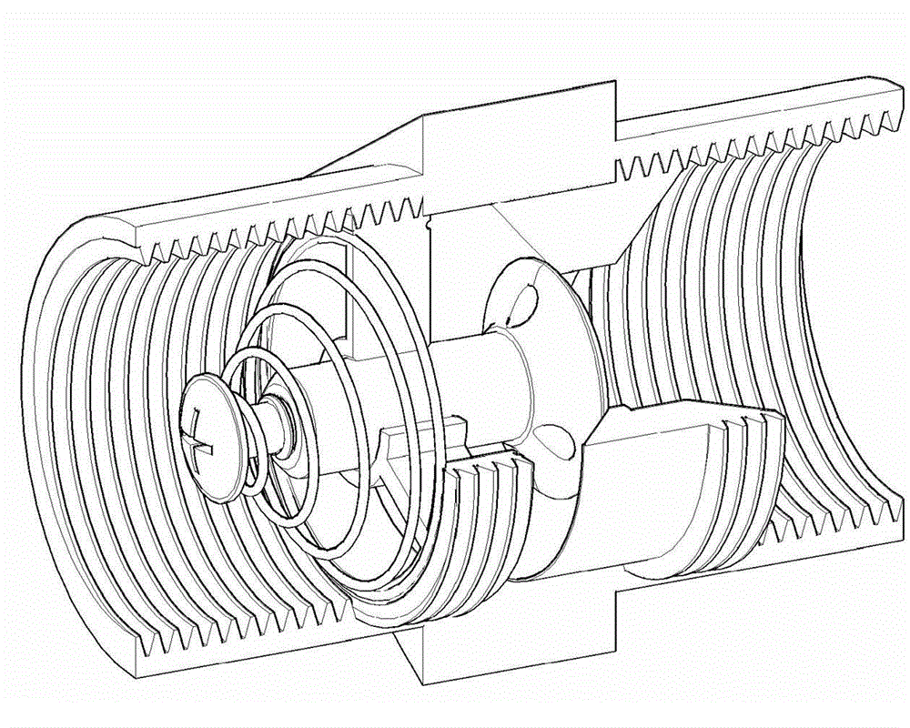
[0018] Such as figure 1 , one A throttle valve is installed in a water pipe joint for use. The water pipe joint is mainly composed of a body 1, a throttle valve 2, a bracket 3, a spring 4, a screw 5 and a valve seat 6.

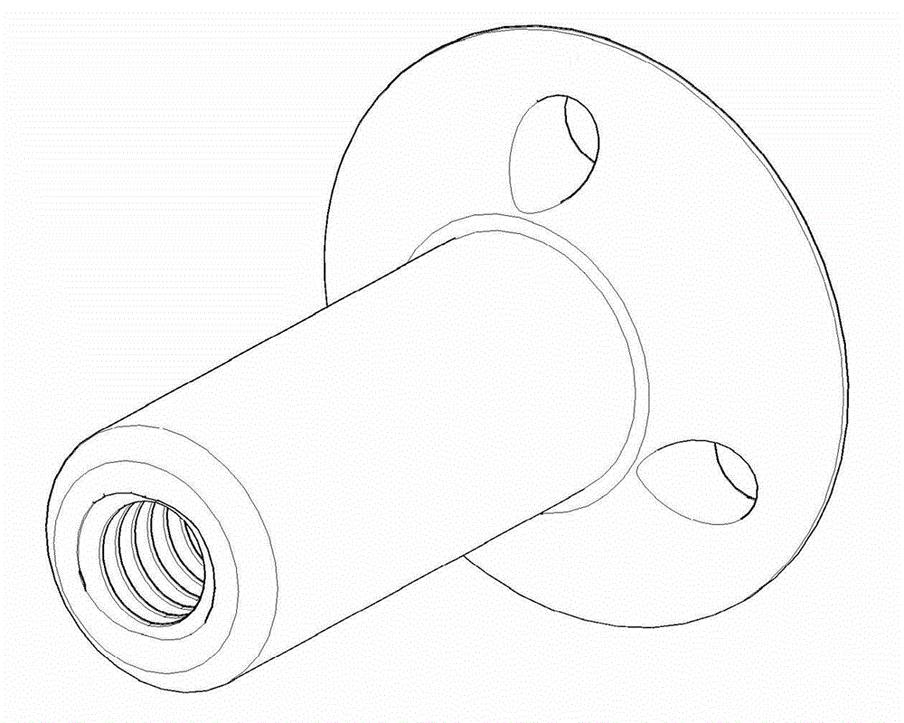
[0019] Throttle valve comprises valve head 21 and valve stem 22 again, is provided with more than two water passage holes 23 that run through valve head on valve head, is provided with the threaded hole coaxial with valve stem on valve stem; Through the fixing hole in the middle of the bracket and then through the spring, screw the screw 5 into the screw hole on the valve stem, fix the spring between the nut and the bracket 3, and then slide the bracket from the body in the direction that the screw cap faces the water inlet. The water inlet end is plugged into the body and fixed.

[0020] The valve seat is installed downstream of the throttle valve in the body, and a through hole is provided on the valve seat, and the wall surface of the through hole facin...


PUM


Abstract

A throttling valve is mounted in a water pipe connector which mainly comprises a body, the throttling valve, a support, a spring, a screw and a valve seat. A water inlet end of a valve head is designed into an arc surface in smooth camber, so that resistance of the valve head to water flow is reduced, and turbulence is reduced; by contraction of a water outlet of a water through hole, discharged water is more concentrated and higher in flushing force.

Description

technical field [0001] The invention relates to a throttling valve capable of adjusting water output, which belongs to the optimization technology of water pipe joints. Background technique [0002] The connection between the water pipes and the connection between the water pipe and the faucet are all realized through joints. At present, these joints mainly play the role of connection and do not have other functions. There are generally two ways to supply water to buildings at present, one is to use a booster pump to send water from bottom to top, and the other is to place a water tank on the roof and use the water level difference to transport water from top to bottom. Regardless of the water delivery method, the water pressure on different floors will be different, resulting in different water output on different floors. [0003] A water pipe joint is disclosed in the patent document No. 201020694120.3. The advantage is that the prestress of the spring can be adjusted by...

Claims


Application Information

Patent Timeline
Patent Type & Authority Applications(China)
IPC IPC(8): F16K17/30F16L29/00
CPCF16K17/30F16K27/02F16K47/023F16L29/00
Inventor 刘毓珍
Owner ZHONGSHAN YAXI ENVIRONMENTAL PROTECTION TECH
Why Eureka
Try Eureka