Eureka AIR delivers breakthrough ideas for toughest innovation challenges, trusted by R&D personnel around the world.

Pipeline optical fiber safety monitoring early warning method and system

A safety monitoring and early warning system technology, which is applied in the pipeline system, mechanical equipment, gas/liquid distribution and storage, etc., can solve the difficulties of multi-point vibration signal detection, identification, judgment and positioning, and cannot realize real-time monitoring of vibration signals. Background Strong noise impact and other issues, to achieve low false alarm rate, resource saving, high precision effect

Active Publication Date: 2015-04-29
PIPECHINA SOUTH CHINA CO
View PDF7 Cites 24 Cited by
  • Summary
  • Abstract
  • Description
  • Claims
  • Application Information

AI Technical Summary

Problems solved by technology

Therefore, this technology can only detect static loss and slowly changing disturbances, and cannot realize real-time monitoring of vibration signals of threat events along the pipeline
[0004] China Invention Patent Application No. 200410020046.6, 200610072879.6, 200610113044.0, 200720169440.5, etc. use multiple optical fibers based on the principle of optical fiber interferometer to form a distributed optical fiber vibration sensor to monitor the vibration signal along the pipeline. Due to the complex environment along the pipeline, the influence of background noise is relatively strong, and the distribution is relatively large. Therefore, it is difficult for this type of technology to detect, identify, judge and locate multi-point vibration signals along the pipeline.

Method used


Image

  • Pipeline optical fiber safety monitoring early warning method and system
  • Pipeline optical fiber safety monitoring early warning method and system
  • Pipeline optical fiber safety monitoring early warning method and system

Examples


Embodiment

[0050] Embodiment. Below in conjunction with accompanying drawing and specific embodiment, this method and system are described in further detail:

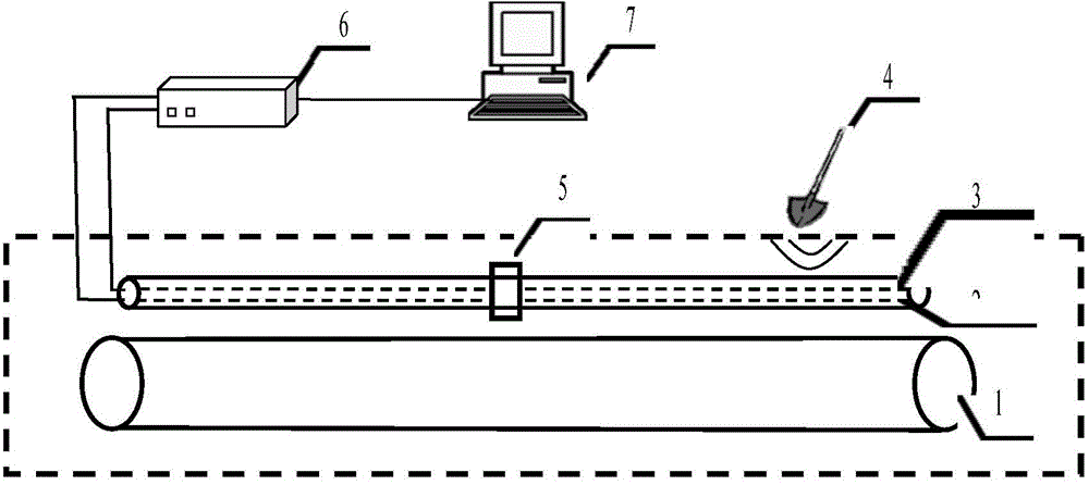
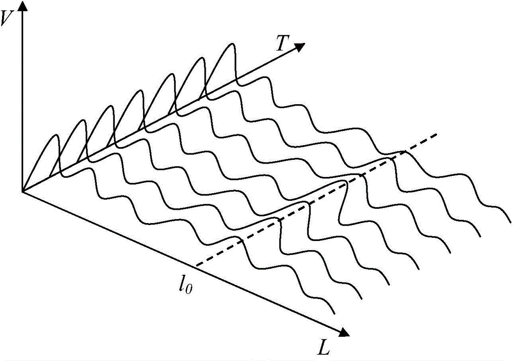
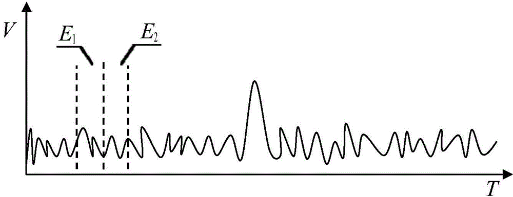
[0051] The principle of this example is as follows figure 1 shown. The vibration signal 4 around the buried pipeline 1 acts on the sensing fiber 2 in the optical cable laid in the same ditch of the pipeline, and the refractive index, length, core diameter, etc. of the fiber will change slightly, causing the phase to change there. The light source in the detection device 6 adopts a highly coherent light source, and the backward Rayleigh scattering in the sensing fiber 2 interferes with each other. Due to the interference, the change of the phase finally causes the change of the intensity of the Rayleigh scattered light. Vibration signals around the pipeline are monitored by detecting this change. The data processing control device 7 can send a relay control signal to the relay amplifier device 5 through the communication optical ...


PUM


Abstract

The invention provides an oil-gas pipeline safety monitoring early warning method and system. The method and the system are characterized in that a communication optical cable is paved around a buried pipeline (1); one of cable cores is taken as a sensing optical fiber (2); one of the cable cores is taken as a communication optical fiber (3); an optical fiber relay amplifying device (5) is arranged along the sensing optical fiber (2); the communication optical fiber (3) is connected with a detection device (6) and a data and control module (7); the data and control module (7) is used for transmitting a relay control signal of the relay amplifying device (5) through the communication optical fiber (3) to realize real-time adjustment of relay amplification; the relay amplifying device can be used for simultaneously amplifying forwardly-transmitted pulse optical waves and a backwardly-transmitted Rayleigh interference optical signal; detected front and back curves are divided with each other to filter background noise, so that the positioning accuracy is increased. By adopting the method and the system, the influence of background noise is low, detection, identification, judgment and positioning functions specific to multi-point vibration signals along a pipeline are realized, and very high detection sensitivity, positioning accuracy and different event identification accuracies are achieved.

Description

technical field [0001] The present invention is an oil and gas pipeline safety monitoring and early warning method and system, in particular, it relates to a distributed optical fiber sensing technology based on the coherent Rayleigh (Φ-OTDR) principle, and involves mechanical vibration measurement, impact measurement and pipeline system technology field. Background technique [0002] As a safe and economical transportation method, pipeline transportation has been widely used all over the world. With the continuous development of the pipeline transportation industry, pipeline safety accidents caused by third-party damage along the pipeline, natural disasters and other factors occur from time to time, seriously affecting the safe operation of the pipeline. In order to maintain the safe operation of pipelines and reduce the occurrence of incidents that endanger pipeline safety, the technology of safe operation and maintenance of pipelines has been highly concerned by scientif...

Claims


Application Information

Patent Timeline
Patent Type & Authority Applications(China)
IPC IPC(8): F17D5/00
Inventor 周琰谭东杰孙巍马云宾刘路孟佳蔡永军邱红辉田孝忠王海明
Owner PIPECHINA SOUTH CHINA CO
Why Eureka
Eureka Blog
Learn More