Measuring method and measuring device for membrane stress

A thin film stress and thin film technology, which is applied in the field of thin film stress measurement methods and measurement devices, can solve problems such as measurement result errors, achieve the effects of reducing measurement errors, improving accuracy, and having a wide range of applications

Active Publication Date: 2015-04-29
EVERDISPLAY OPTRONICS (SHANGHAI) CO LTD
View PDF2 Cites 5 Cited by
  • Summary
  • Abstract
  • Description
  • Claims
  • Application Information

AI Technical Summary

Problems solved by technology

[0006] When the light beam is moving, the measurement process will be affected by the machine itself, vibration, dead pixels, m

Method used


Image

  • Measuring method and measuring device for membrane stress
  • Measuring method and measuring device for membrane stress
  • Measuring method and measuring device for membrane stress

Examples


Embodiment Construction

[0037] In order to understand the technical content of the present invention more clearly, the following examples are given in detail.

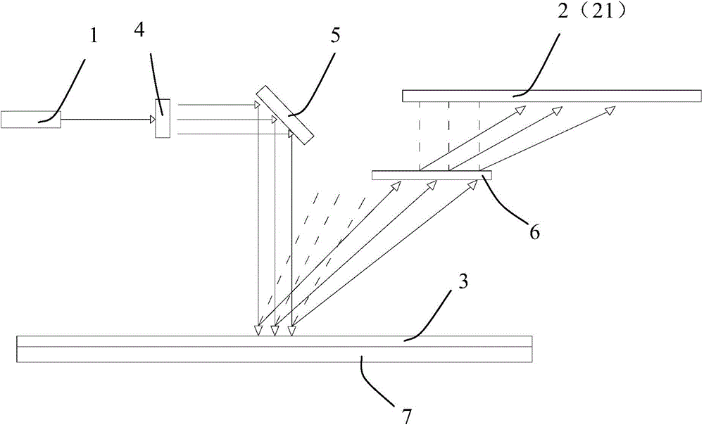
[0038] see figure 2 Shown is a schematic diagram of the structure of the thin film stress measurement device of the present invention.

[0039] In one embodiment, as figure 2 As shown, the film stress measuring device of the present invention includes a laser emitter 1 and a detector 2 .

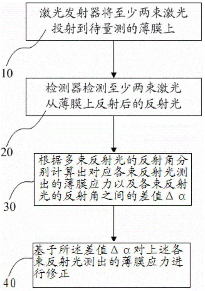
[0040] Utilize the device of this embodiment to carry out the film stress measurement method, such as image 3 shown, including the following steps:

[0041] Step (10) The laser transmitter 1 projects at least two laser beams onto the film 3 to be measured;

[0042] Step (20) the detector 2 detects the reflected light of the at least two laser beams reflected from the film 3;

[0043] Step (30) Calculate the film stress measured corresponding to each beam of reflected light and the difference Δα between the reflection angles of each beam of reflected...


PUM


Abstract

The invention relates to a measuring method and measuring device for membrane stress and belongs to the technical field of measurement. In the measuring method and the measuring device for membrane stress, at least two laser beams are projected to a membrane to be measured by a laser transmitter, so that after a detector receives reflection light reflected by the membrane, the membrane stress can be corrected according to difference values delta alpha of reflection angles of multiple reflection light, so that an error in measurement can be lowered greatly; besides, the measuring device also includes a revolving mirror group which can project over-ranging reflection light to a laser receiving unit, thereby enlarging the measuring range, and further improving the precision of a measuring result; the measuring device for the membrane stress provided by the invention is simple in structure, low in cost,simple and convenient in application manner of the measuring method and wider in application range.

Description

technical field [0001] The invention relates to the technical field of measurement, in particular to the technical field of thin film stress measurement, in particular to a thin film stress measurement method and a measurement device. Background technique [0002] At present, the commonly used machine for stress measurement is an independent offline mode. The measurement substrate is mostly a silicon wafer. A single beam laser is projected onto the film, and only a single reflection angle is measured to calculate the stress value. The measurement method is as figure 1 shown. [0003] In this mode, a thin film is attached to a substrate such as a silicon wafer. Since the physical constants of the substrate and the thin film are different, stress will be generated and the substrate will deform. The deformation caused by a uniformly attached film is manifested as substrate warping. According to the laser reflection angle scanned on the substrate to calculate the radius of cur...

Claims


Application Information

Patent Timeline
IPC IPC(8): G01L1/24
Inventor 刘冲彭思君杨飞
Owner EVERDISPLAY OPTRONICS (SHANGHAI) CO LTD
Why Eureka
Try Eureka