
Method for determining radar target characteristic measuring synchronous scattering point area of compact range

A radar target and constriction field technology, applied in radio wave measurement systems, instruments, etc., to solve problems such as inability to eliminate

Inactive Publication Date: 2015-04-29
BEIJING INST OF RADIO METROLOGY & MEASUREMENT
View PDF4 Cites 7 Cited by
  • Summary
  • Abstract
  • Description
  • Claims
  • Application Information

AI Technical Summary

Problems solved by technology

However, this processing method cannot eliminate the interference scattering signal emitted by the compact field feed source in the compact field, scattered by the scattering points in the compact field to the compact field feed source, and the transmitted wave of the compact field feed source is reflected by the compact field reflective surface. Arrive at the target to be measured, and then return to the scattered signal of the target to be measured at the same time as the scattered signal of the target to be measured by the original path, that is, if the interference scattered signal is synchronized with the time of the target to be measured way, cannot be eliminated

Method used


Image

  • Method for determining radar target characteristic measuring synchronous scattering point area of compact range
  • Method for determining radar target characteristic measuring synchronous scattering point area of compact range
  • Method for determining radar target characteristic measuring synchronous scattering point area of compact range

Examples


Embodiment Construction

[0038] In order to illustrate the present invention more clearly, the present invention will be further described below in conjunction with preferred embodiments and accompanying drawings. Similar parts in the figures are denoted by the same reference numerals. Those skilled in the art should understand that the content specifically described below is illustrative rather than restrictive, and should not limit the protection scope of the present invention.

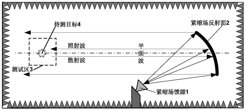
[0039] The invention discloses a method for determining a scatter point area, and in particular discloses a method for determining a scatter point area synchronously with a compact field radar target characteristic measurement.

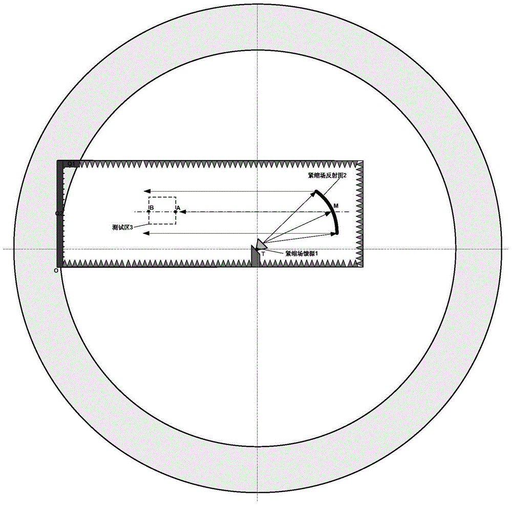
[0040]Establish a three-dimensional rectangular coordinate system in the anechoic chamber of the compact field; the three-dimensional rectangular coordinate system takes any corner of the anechoic chamber of the compact field as the origin O of the coordinate system, takes the length direction as t...


PUM


Abstract

The invention discloses a method for determining a radar target characteristic measuring synchronous scattering point area of a compact range. The method comprises the following steps: building a three-dimensional rectangular coordinate system in a dark chamber of the compact range; determining position of a feed source of the compact range in the three-dimensional rectangular coordinate system; determining position of a reflective surface of the compact range according to the position of the feed source of the compact range and position of a test area; taking the position of the feed source of the compact range as a circle center and taking a furthest distance and a shortest distance generated when reflection wave of the feed source of the compact range is reflected by the reflective surface of the compact range and directly arrives at a target to be tested in an area to be tested as semi-diameter to build two spherical surfaces in the dark chamber of the compact range; forming a synchronous scattering point area by using the two spherical surfaces and a space between the two spherical surfaces. The method can be used for quickly finding a maximum synchronous scattering point area in the compact range with scattering signals which have interference effects and arrive at the feed source of the compact range simultaneously with scattering signals of the target to be tested.

Description

technical field [0001] The invention relates to a method for determining the area of ​​a scattering point. More specifically, it relates to a method for determining the area of ​​scattered points synchronously with measurement of characteristics of a compact field radar target. Background technique [0002] With the development of stealth and anti-stealth technology, the requirements for the measurement accuracy of radar target characteristics are getting higher and higher. In order to meet the far-field conditions of classic radar target characteristic measurement, the compact field has become the most commonly used method for radar target characteristic measurement. Schematic diagram of indoor compact field radar target characteristic measurement as shown in figure 1 As shown, the compact field feed emits spherical electromagnetic waves, which are converted into plane waves to irradiate the target to be measured after being reflected by the compact field reflector. Feed...

Claims


Application Information

Patent Timeline
IPC IPC(8): G01S7/41
CPCG01S7/41
Inventor 马永光杨金涛康宁何锦
Owner BEIJING INST OF RADIO METROLOGY & MEASUREMENT
Learn More