
Ultralow background alpha ionization chamber

An ionization chamber and background technology, applied in circuits, discharge tubes, electrical components, etc., can solve the problem of difficult to meet the needs of ultra-low background alpha sample measurement, alpha emissivity screening and rejection, difficult to meet ultra-low cost Problems such as the need for bottom measurement

Active Publication Date: 2015-04-29
CHINA INSTITUTE OF ATOMIC ENERGY
View PDF3 Cites 6 Cited by
  • Summary
  • Abstract
  • Description
  • Claims
  • Application Information

AI Technical Summary

Problems solved by technology

This method has reached its limit, and it is still difficult to meet the demand for the measurement of ultra-low background α samples
Similarly, for semiconductor detectors, in addition to the α background of the detector material itself, it is also affected by cosmic rays, and it is difficult to meet the needs of ultra-low background measurement
At present, there is no ultra-low background alpha ionization chamber that can screen and reject the alpha emission rate of the detector material itself

Method used


Image

  • Ultralow background alpha ionization chamber
  • Ultralow background alpha ionization chamber
  • Ultralow background alpha ionization chamber

Examples


Embodiment 1

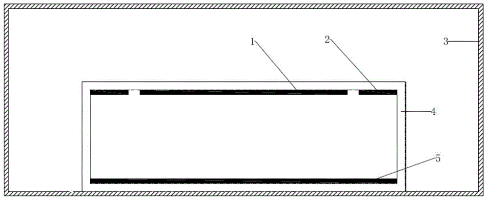
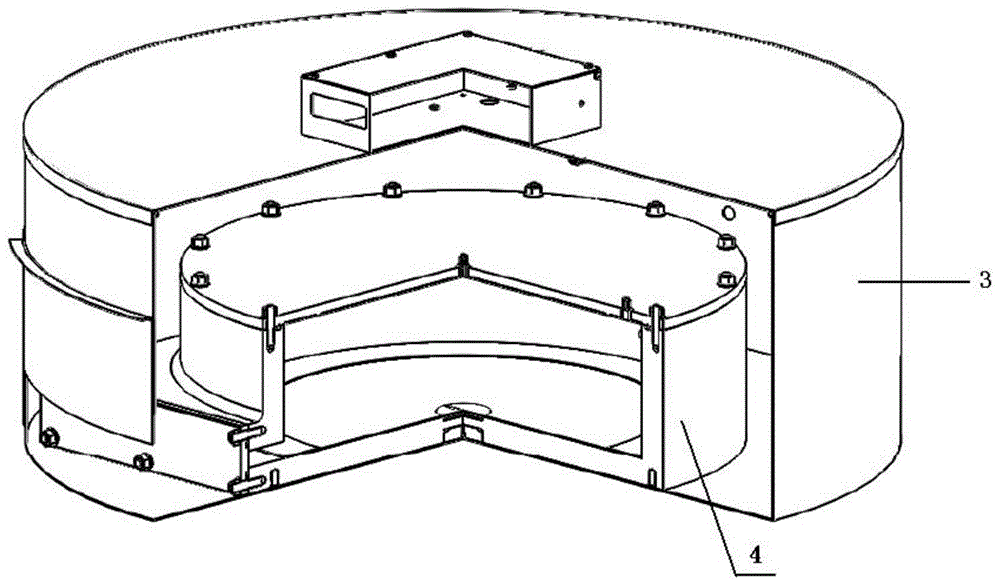
[0031] Ultra-low background alpha ionization chambers, such as figure 1 and figure 2 As shown, the ionization chamber includes a cylindrical cavity and a shielding body, wherein the cylindrical cavity is located in the shielding body and at the center of the bottom of the shielding body. The material of the cavity is nylon, the height is 15cm, and the diameter is 55cm, and the material of the shielding body is stainless steel. A circular anode and a ring-shaped protective electrode are arranged on the top and lower surface of the cylindrical cavity, and both the anode and the protective electrode are used as collectors, and the material is copper. The diameter of the anode is 44cm, the width of the guard ring is 5cm, the guard is located outside the anode and there is a 0.1cm gap between the anode and the anode for insulation, the anode, the guard and the center of the top of the cavity are in the same position; the bottom of the cavity is set It is a sample holder made of ...

Embodiment 2

[0034] The difference from Example 1 is that the sample holder at the bottom of the cavity is a drawer structure, which is convenient for sample change. A gap of 0.5 cm was left between the anode and the guard electrode. The width of the protective pole is 1.5 times the range of alpha particles in the working gas of the ionization chamber under normal pressure.

Embodiment 3

[0036] The difference from Example 1 is that there is a gap of 1 cm between the anode and the guard electrode, and the width of the guard electrode is 0.5 times the range of alpha particles in the working gas of the ionization chamber under normal pressure.


PUM


Abstract

The invention belongs to the technical field of radioactivity measurement and discloses an ultralow background alpha ionization chamber for measuring an ultralow background alpha sample. The ionization chamber comprises a cylindrical cavity and a shielding body, wherein the cavity is positioned in the shielding body and positioned in the central position at the bottom of the shielding body; a circular anode and an annular protection pole are arranged on the lower surface of the top of the cavity, an anode and the protection pole have the same working voltage and are used as collection poles, the anode, the protection pole and the position of the center of a circle of the top of the cylindrical cavity are consistent, and the protection pole is positioned on the outer side of the anode and is insulated with the anode; a sample support is arranged at the bottom of the cavity and used as a cathode at the same time; the distance between the anode and the cathode is 2-5 times the range of alpha particles in working gas of the ionization chamber at normal pressure. The ionization chamber has the characteristics that the ionization chamber can discriminate and eliminate alpha emissivity of material of the ionization chamber and be used for measuring the ultralow background alpha sample.

Description

technical field [0001] The invention belongs to the technical field of radioactivity measurement, and in particular relates to an ultra-low background alpha ionization chamber for measuring ultra-low background alpha samples. Background technique [0002] The demand for low background or even ultra-low background α measurement is increasing in environmental monitoring, basic physics experiments, new material production, especially in the production of microelectronic component packaging materials. Especially as the semiconductor production process enters the finer nanometer level, the operating voltage becomes lower, and the soft error (Soft Error) caused by ionizing radiation will increase exponentially under this condition. In order for this error rate not to affect the performance of electronic products, the alpha radiation in the packaging material is required to be as small as possible. Therefore, there is an urgent need for corresponding ultra-low background α measuri...

Claims


Application Information

Patent Timeline
Patent Type & Authority Applications(China)
IPC IPC(8): H01J47/02G01T7/00
CPCG01T7/00H01J47/02H01J47/026
Inventor 姚顺和杨巧玲姚艳玲吕晓侠刁立军陈细林汪建清郭晓清孟军邢雨
Owner CHINA INSTITUTE OF ATOMIC ENERGY
Learn More