Hybrid direct-current transmission converter and direct-current transmission device

A hybrid DC transmission and converter technology, applied in the fields of HVDC and UHV DC transmission, can solve the problems of increasing the loss and cost of the DC system

Active Publication Date: 2015-04-29
NR ELECTRIC CO LTD +1
View PDF3 Cites 41 Cited by
  • Summary
  • Abstract
  • Description
  • Claims
  • Application Information

AI Technical Summary

Problems solved by technology

The above-mentioned converter structures have additional circuits only to e

Method used


Image

  • Hybrid direct-current transmission converter and direct-current transmission device
  • Hybrid direct-current transmission converter and direct-current transmission device
  • Hybrid direct-current transmission converter and direct-current transmission device

Examples


Embodiment 1

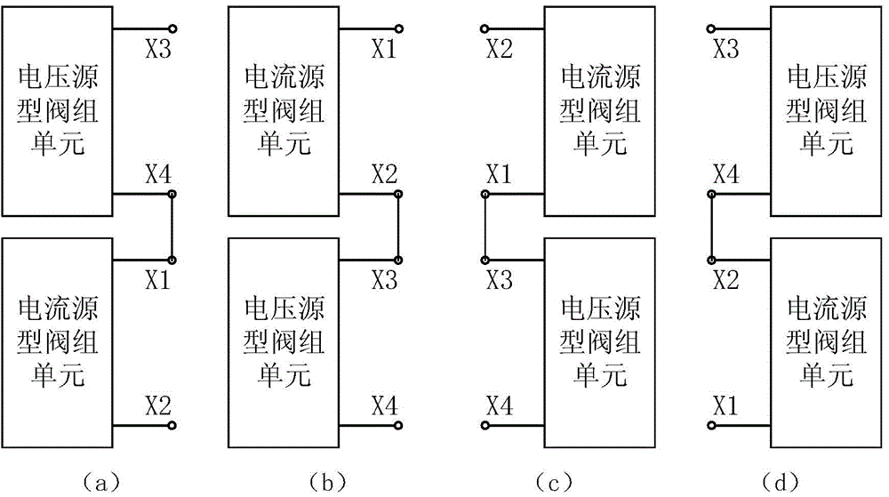
[0066] Figure 6 It shows that the HVDC power transmission device is all composed of Figure 5 An embodiment composed of the four topologies shown, which connect the rectifier station 20 and the inverter station 21 through the DC line 15 . The rectifier station 20 consists of topological structures (1) 16 and (2) 17 to form its negative converter and positive converter respectively, and the inverter station 21 consists of topological structures (3) 18 and (4) 19 to form its positive converter respectively. converter and negative pole converter. Valve group 1 is a current source valve group, which is connected to the 8 secondary windings of the thyristor-based current source high-voltage direct current transmission transformer, and valve group 2 is a voltage source type valve group, which is connected to the high voltage direct current transmission transformer based on a voltage source converter. The 9 secondary windings of the transformer are connected. It should be pointed...

Embodiment 2

[0071] Figure 7 It shows that the HVDC power transmission device consists of a traditional current source valve group converter and Figure 5An example of two topologies is shown. The rectifier station 20 of the HVDC power transmission device is composed of a topology 24 in which current source valve units are connected in series, and the inverter station 21 is composed of topological structures (3) 18 and (4) 19 to form its positive converter and negative converter respectively. Valve group 1 is a current source valve group, which is connected to the 8 secondary windings of the thyristor-based current source high-voltage direct current transmission transformer, and valve group 2 is a voltage source type valve group, which is connected to the high voltage direct current transmission transformer based on a voltage source converter. The 9 secondary windings of the transformer are connected. The rectifier station 20 is configured with an AC filter 23 to filter harmonics and pr...


PUM


Abstract

The invention discloses a hybrid direct-current transmission converter. The hybrid direct-current transmission converter is provided with four topological structures which are series connection circuits formed by combining anodes and cathodes of current source type valve group units and positive electrodes and negative electrodes of voltage source type valve group units in different modes. Each current source type valve group unit only comprises a current source type valve group or comprises a current source type valve group and a bypass switch or comprises a current source type valve group, a bypass switch and a disconnecting link assembly. Each voltage source type valve group unit only comprises a voltage source type valve group or comprises a voltage source type valve group and a bypass circuit or comprises a voltage source type valve group, a bypass circuit and a disconnecting link assembly. A direct-current transmission device composed of the hybrid direct-current transmission converter effectively solves the problem of commutation failures of a direct-current transmission system based on thyristors and the problem of direct-current faults of a direct-current transmission system based on a voltage source converter, and has the advantages that loss is low, a reactive compensation device is not needed or a small number of reactive compensation devices are needed, and the direct-current transmission device can be connected into a passive alternating-current system and has the inverse power output function.

Description

technical field [0001] The invention belongs to the fields of high-voltage direct current transmission and ultra-high voltage direct current transmission, and in particular relates to a direct current transmission converter in which a thyristor-based current source valve group unit and a voltage source valve group unit based on a fully controllable power semiconductor that can be turned off are connected in series. streamer structure. Background technique [0002] The advantage of current source HVDC transmission based on thyristors is that the loss of the converter is small, and the DC system can be restarted by shifting the phase when a DC line fault occurs; the disadvantage is that the converter on the inverter side works in active inverter and cannot be connected to wireless Source system; the inverter side is connected to the weak AC system, and commutation failure is prone to occur after disturbance; the reactive power consumption is large, and the voltage and current ...

Claims


Application Information

Patent Timeline
IPC IPC(8): H02J3/36H02J9/06
CPCH02J3/36Y02B70/30Y02E60/60Y04S20/20
Inventor 卢东斌
Owner NR ELECTRIC CO LTD
Why Eureka
Try Eureka