Control method of direct-current photovoltaic power generating modules

A photovoltaic power generation module and control method technology, applied in photovoltaic power generation, AC network circuits, electrical components, etc., can solve the complex structure of photovoltaic power generation DC-DC converter system, reduce system energy conversion efficiency, and difficult to obtain component status information, etc. problems, achieve high component electrical parameter mismatch capability, fast fault diagnosis and fault location, and solve the effect of hot spot effect

Active Publication Date: 2015-04-29
山东永锦电气股份有限公司
View PDF5 Cites 7 Cited by
  • Summary
  • Abstract
  • Description
  • Claims
  • Application Information

AI Technical Summary

Problems solved by technology

[0002] At present, the commonly used photovoltaic power generation systems mainly include centralized, series, and multi-branch structures, but their disadvantages are: there are series or parallel connections of photovoltaic modules in the system, and the maximum power point tracking of the system is for the entire series-parallel photovoltaic array. Or module strings, it is impossible to ensure that each module operates at the maximum power point, the anti-shading ability is poor, and hot spots may even be formed, resulting in module damage, low system reliability, greatly reducing the energy conversion efficiency of the system, and it is also difficult to obtain every status information for each component
It can be seen that the DC-DC converter for photovoltaic power generation and its control method have problems such as complex system structure, complex control, difficult construction, and high cost, and it does not involve the communication problem of each converter.

Method used


Image

  • Control method of direct-current photovoltaic power generating modules
  • Control method of direct-current photovoltaic power generating modules

Examples


Embodiment Construction

[0030] The present invention will be described in further detail below in conjunction with the accompanying drawings.

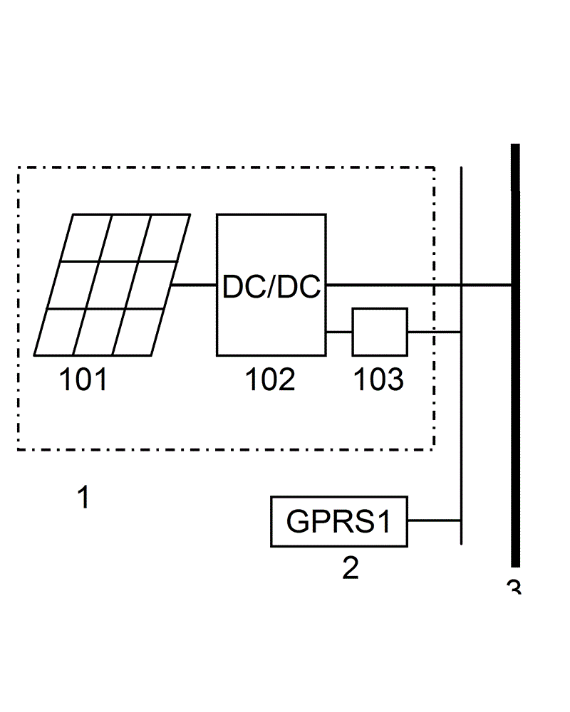
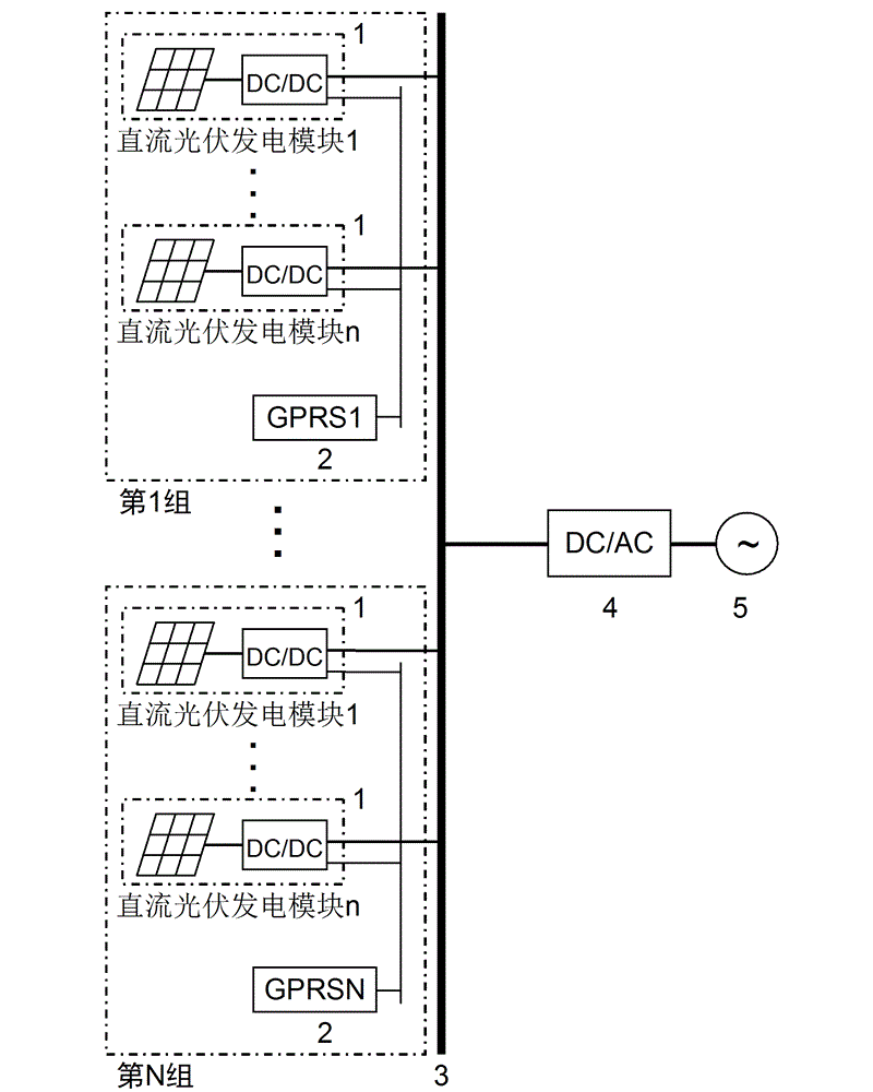
[0031] as attached figure 1 As shown, the present invention is a control method of a DC photovoltaic power generation module. The DC photovoltaic power generation module 1 is composed of a photovoltaic module 101, a DC micro-converter 102, and a communication module 103. One end of the DC micro-converter 102 is connected to the photovoltaic module 101. The other end is connected to the DC bus 3, and the DC micro-converter 101 is connected with its own control loop, and the control loop is connected to its communication module 103 to realize DC boost, maximum power point tracking (MPPT) and communication functions, and completely solve shadows, etc. The formed hot spot effect greatly improves the power generation efficiency of the system.

[0032] The DC micro-converter 102 adopts a DC-AC-DC structure. First, through DC-AC inversion, the DC power output by th...


PUM


Abstract

The invention relates to a control method of direct-current photovoltaic power generating modules, and belongs to the technical field of photovoltaic power generation. The method comprises the steps of firstly, forming a photovoltaic power generation system by adopting direct-current photovoltaic power generating modules, GPRS modules, a direct-current bus, an inverter and an alternating-current electric network; connecting all the direct-current photovoltaic power generating modules as basic units in parallel with the direct-current bus, meanwhile, dividing all the direct-current photovoltaic power generating modules into a plurality of groups, wherein each group comprises n direct-current photovoltaic power generating modules and a GPRS module, and carrying out wireless communication with an upper computer; secondly, detecting and judging the malfunction according to output voltage of a photovoltaic component and output power of direct-current photovoltaic power generating modules; and finally, determining the operation state of each direct-current photovoltaic power generating module according to the voltage of the direct-current bus. According to the invention, the structure is simple; the control is flexible and convenient; the malfunction diagnosis and positioning are rapid and accurate; the hot spot effect formed by shadows and the like can be solved completely; the maximal power generating efficiency is realized; the control method is especially suitable for distribution type photovoltaic power stations.

Description

technical field [0001] The invention relates to a control method, in particular to a control method of a DC photovoltaic power generation module, which belongs to the technical field of photovoltaic power generation. Background technique [0002] At present, the commonly used photovoltaic power generation systems mainly include centralized, series, and multi-branch structures, but their disadvantages are: there are series or parallel connections of photovoltaic modules in the system, and the maximum power point tracking of the system is for the entire series-parallel photovoltaic array. Or module strings, it is impossible to ensure that each module operates at the maximum power point, the anti-shading ability is poor, and hot spots may even be formed, resulting in module damage, low system reliability, greatly reducing the energy conversion efficiency of the system, and it is also difficult to obtain every status information of a component. [0003] In view of the above sho...

Claims


Application Information

Patent Timeline
Patent Type & Authority Applications(China)
IPC IPC(8): H02J3/38
CPCH02J3/385Y02E10/56
Inventor 蔡彬褚晓广郑晓明袁延梅魏川栋
Owner 山东永锦电气股份有限公司
Why Eureka
Try Eureka