Method for preparing thermal barrier coating bonding layer by utilizing laser powder deposition technology

A technology of laser powder and thermal barrier coating, which is applied in the direction of coating, metal material coating process, fusion spraying, etc., can solve the problems of low porosity and coating thermal conductivity, etc., to reduce oxidation and slow down growth The effect of low rate and oxidation rate

Inactive Publication Date: 2015-05-06
SHANGHAI JIAO TONG UNIV +1
View PDF2 Cites 14 Cited by
  • Summary
  • Abstract
  • Description
  • Claims
  • Application Information

AI Technical Summary

Problems solved by technology

This patent application is aimed at the preparation of functionally graded thermal barrier coatings, the coatings prepared by this method will inevitably reduce the thermal conductivity of the coating due to the low porosity and the simultaneous mixing of metal partic

Method used


Image

  • Method for preparing thermal barrier coating bonding layer by utilizing laser powder deposition technology
  • Method for preparing thermal barrier coating bonding layer by utilizing laser powder deposition technology

Examples


Embodiment 1

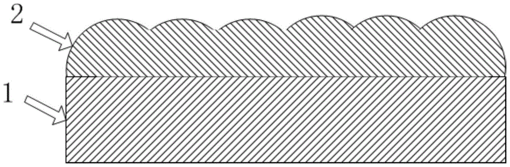
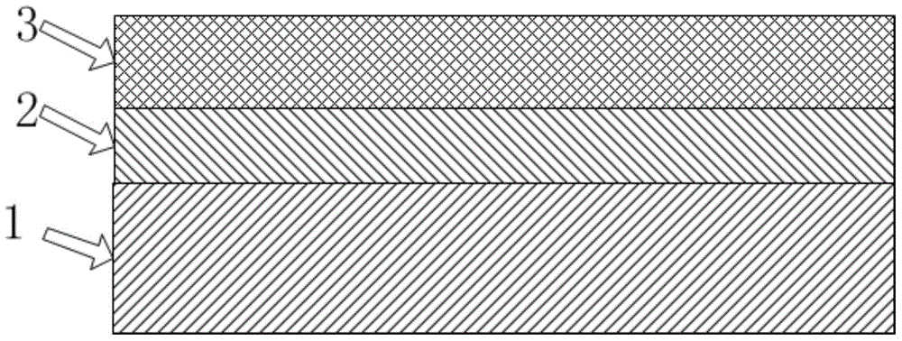
[0031] First, the Hastelloy-X alloy is cleaned and sandblasted. The metal bonding layer is prepared by laser powder spraying technology, and its main component is NiCrAlY. The metal powder is melted by laser, and the program is set to deposit the bonding layer line by line on the substrate. The width of the structural unit is about 500 μm, the height is about 200 μm, the overlap rate is 25%, the laser power is 130W, and the scanning rate is 10mm / s. , the laser spot diameter is 0.5mm, the powder feeding rate is 3g / min, and the Ar gas flow rate is 6L / min. The uncontrollable roughness and particles adhering to the surface caused by the laser powder spraying process are eliminated by sandblasting, in which the Al 2 o 3 The particle size is 60 mesh, and the blasting pressure is 0.5MPa. Finally, an 8YSZ coating with a thickness of 200 μm was obtained by atmospheric plasma spraying, the spraying current was 400 A, the voltage was 150 V, the Ar flow rate was 45 L / min, and the H 2 ...

Embodiment 2

[0033] First, the nickel-based single crystal substrate is cleaned and sandblasted to obtain a clean surface with moderate roughness. Then a metal bonding layer whose main component is NiCoCrAlY and whose thickness is 300 μm is prepared by laser powder deposition technology. The specific parameters are: laser power 130W, laser spot diameter 0.5mm, laser mode continuous, scan rate 7mm / s, structural unit width 500μm, height about 200μm, powder feeding rate 3g / min, Ar The air flow is 6L / min. Then the surface of the bonding layer was sandblasted, the sandblasting pressure was 0.7MPa, Al 2 o 3 The particle size is 60 mesh, so that the thickness of the bonding layer is reduced to 150 μm. Finally, a ceramic insulation layer with a main component of 8YSZ and a thickness of 250 μm was obtained by atmospheric plasma spraying. Among them, the spraying current is 400A, the voltage is 150V, the Ar gas flow rate is 60L / min, and the H 2 The flow rate is 20L / min, the distance between the...


PUM


Abstract

The invention relates to a method for preparing a thermal barrier coating bonding layer by utilizing a laser powder deposition technology. The method comprises the steps of sequentially carrying out rust removal and deoiling sand blasting treatment on a metal basal body; depositing a metal bonding layer on the metal basal body by virtue of laser powder; processing the surface of the metal bonding layer by virtue of sand blasting, and obtaining the certain surface coarseness and a certain bonding layer thickness; depositing a ceramic thermal barrier layer on the metal bonding layer by virtue of plasma spraying or electron beam physical gas phase deposition. Compared with the prior art, the metal bonding layer is prepared by virtue of the laser powder deposition technology, the conventional plasma spraying method and the conventional electron beam physical gas phase deposition method are substituted, and the obtained metal bonding layer is compact in structure and uniform in components, so that the service life of the thermal barrier coating can be prolonged.

Description

technical field [0001] The invention relates to the field of thermal barrier coatings, in particular to a method for preparing a bonding layer of thermal barrier coatings by laser powder deposition technology. Background technique [0002] The thermal barrier coating can effectively reduce the temperature of the alloy surface by adding a ceramic insulation layer with low thermal conductivity between the high-temperature gas and the superalloy. This makes it possible for superalloys to serve in environments near or above their melting point. In high-temperature engines, the application of thermal barrier coatings can effectively improve fuel efficiency and engine thrust-to-weight ratio. [0003] The structure of thermal barrier coatings widely used and researched mainly includes ceramic surface thermal insulation layer and metal bonding layer. The most mature material for the application of ceramic insulation layer is 6-8wt% Y 2 o 3 Stabilized ZrO 2 , Its low thermal con...

Claims


Application Information

Patent Timeline
IPC IPC(8): C23C24/10C23C4/10C23C4/12C23C4/134
Inventor 罗丽荣赵晓峰郭芳威周新义
Owner SHANGHAI JIAO TONG UNIV
Why Eureka
Try Eureka