Power trench mosfet rectifier

Active Publication Date: 2011-11-24
BCD SHANGHAI MICRO ELECTRONICS CO LTD
View PDF3 Cites 21 Cited by
  • Summary
  • Abstract
  • Description
  • Claims
  • Application Information

AI Technical Summary

Benefits of technology

[0006]As described above, conventional rectifying devices suffer from various limitations. Embodiments

Problems solved by technology

As described above, conventional rectifyin

Method used


Image

  • Power trench mosfet rectifier
  • Power trench mosfet rectifier
  • Power trench mosfet rectifier

Examples


Embodiment Construction

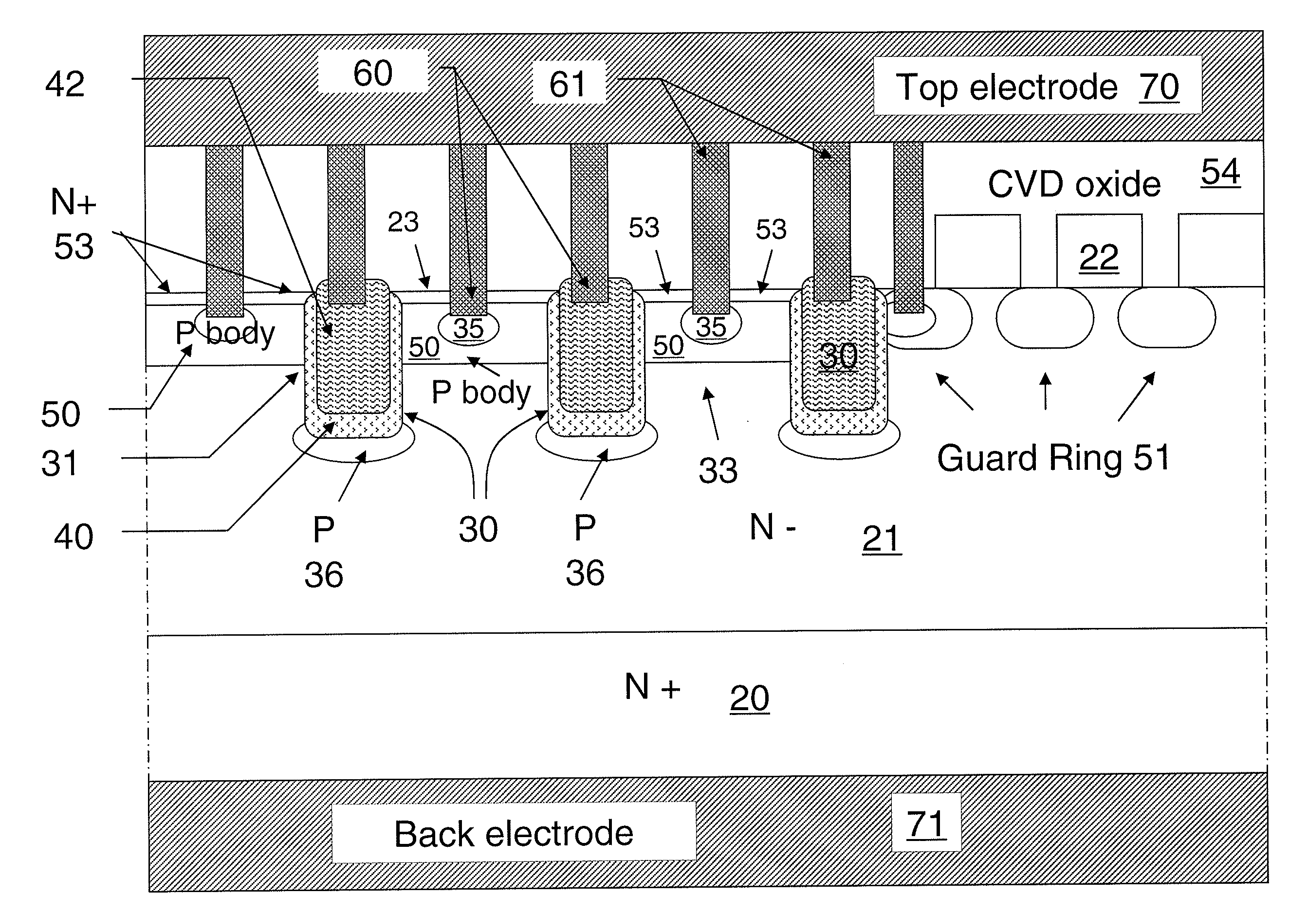
[0017]As described above, PN diodes with high turn-on voltages are unsuited for modern power semiconductor rectifiers applications. As an alternative, Schottky diodes are characterized by a low turn-on voltage and fast turn off, but Schottky diodes have several drawbacks. For example, Schottky diodes rectifiers tend to have high leakage current under high reverse voltage due to “barrier height lowering effect”. This will cause high power dissipation and reliability problems. Further, when the reverse blocking capability is increased to 200V, the forward drop of the Schottky rectifier can approach that of a P-i-N rectifier, making them generally unacceptable for use in high-voltage power circuits. On the other hand, a P-i-N rectifier has its own drawbacks. The P-i-N rectifier is minority carriers device which produces a poor reverse recovery characteristic.

[0018]As a result, more and more attention is paid to synchronous rectification method using a synchronous rectifier (SR) or an M...


PUM


Abstract

A trench MOSFET rectifier includes oxide layers having different thicknesses formed in different regions of the devices. The rectifying device also includes a source region of first conductivity type at a surface of each mesa region and a body region of a second conductivity type beneath each source region. The rectifying device also includes a dielectric layer lining the bottom and sidewall surfaces of the trenches, the portion of the dielectric layer on the bottom surface being thicker than the portion on the sidewall surface. A doped region underlies each of the first plurality of trenches. A polycrystalline silicon region filling each of the first plurality of trenches to form a gate region in each trench. A conductive material fills a plurality of contact trenches and forms ohmic contacts with the source region, body region, and gate region.

Description

CROSS-REFERENCES TO RELATED APPLICATIONS[0001]This application claims priority to Chinese Patent Application No. ______, filed May 17, 2010, by inventors Tao Long et. al., commonly assigned and incorporated in its entirety by reference herein for all purposes.BACKGROUND OF THE INVENTION[0002]Embodiments of the present invention relate generally to semiconductor devices. More particularly, some embodiments of the invention relate to a power semiconductor rectifier device and a method of making the device.[0003]Power semiconductor rectifiers are used extensively in power supplies and power converters. In order to provide a DC voltage, diode rectification has been used for many years in switching mode power supplies. However, the scaling down of semiconductor technology calls for lower voltage and larger current power supply. A PN diode is typically can have a forward voltage drop of around 0.6-0.8V. For 3V output application, this limits the theoretical efficiency of a DC / DC power con...

Claims


Application Information

Patent Timeline
IPC IPC(8): H01L29/78H01L21/336
CPCH01L29/0619H01L29/861H01L29/0692H01L29/0623
Inventor LONG, TAOWANG, YIMINGJIN, ZHONGYUAN
Owner BCD SHANGHAI MICRO ELECTRONICS CO LTD
Why Eureka
Try Eureka