
Prefabricated reinforced concrete column with high-performance concrete frame and construction method

A high-performance concrete and reinforced concrete column technology, applied in the direction of columns, piers, pillars, etc., can solve the problems of shortened construction period, poor overall performance, unfavorable earthquake resistance, etc. Effect

Inactive Publication Date: 2015-05-06
XI'AN UNIVERSITY OF ARCHITECTURE AND TECHNOLOGY
View PDF4 Cites 19 Cited by
  • Summary
  • Abstract
  • Description
  • Claims
  • Application Information

AI Technical Summary

Problems solved by technology

Compared with the cast-in-place concrete structure, the prefabricated structure can make the production of building components not affected and restricted by seasons, and realize industrial production. Since the components are poured and maintained in the factory, the quality of the components can be guaranteed, and the construction period is greatly shortened. Accelerate the construction progress and save a lot of formwork support, but it also has many shortcomings, such as poor overall performance, poor impermeability, unfavorable earthquake resistance, and certain deficiencies in use and aesthetics

Method used


Image

  • Prefabricated reinforced concrete column with high-performance concrete frame and construction method
  • Prefabricated reinforced concrete column with high-performance concrete frame and construction method
  • Prefabricated reinforced concrete column with high-performance concrete frame and construction method

Examples


Embodiment Construction

[0033] The implementation of the present invention will be described in detail below in conjunction with the drawings and examples.

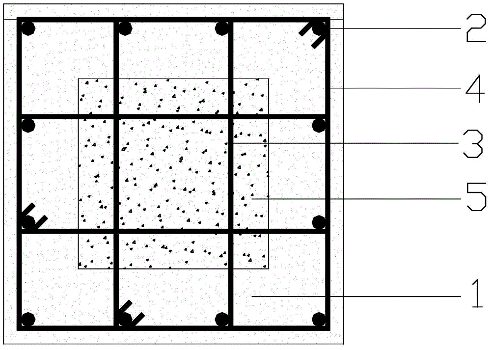
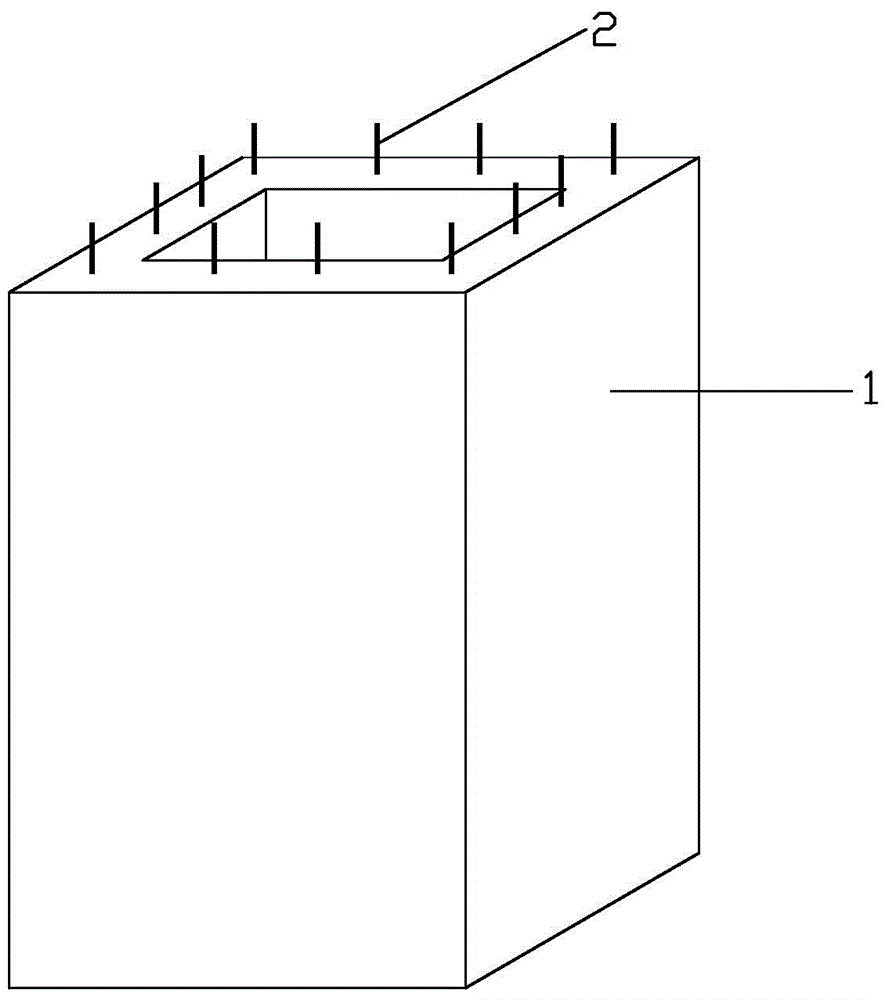
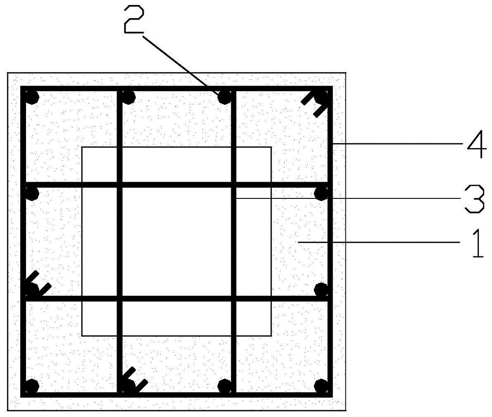
[0034] The present invention is a prefabricated assembled reinforced concrete column with a high-performance concrete frame, which adopts the idea of ​​partially prefabricated assembled part cast-in-place, and is composed of a prefabricated part and a cast-in-place part, such as Figure 1 to Figure 5 As shown, it includes: prefabricated high-performance concrete hollow column 1, longitudinal reinforcement 2 arranged in the prefabricated high-performance concrete hollow column 1 along the column length direction, steel bars 3 and The stirrup 4 and the steel bar 3 span the central cavity of the prefabricated high-performance concrete hollow column 1, and the ends of the steel bar 3 are connected to the inner side of the stirrup 4 and the cast-in-place filling in the central cavity of the prefabricated high-performance concrete hollow column 1 Ordi...


PUM


Abstract

The invention discloses a prefabricated reinforced concrete column with a high-performance concrete frame, which adopts a thought of partially prefabricating and partially casting in situ, and is composed of a prefabricated part and a cast-in-situ part. The prefabricated reinforced concrete column with the high-performance concrete frame comprises a prefabricated high-performance concrete hollow column, longitudinal bars arranged in the prefabricated high-performance concrete hollow column along the length direction of the column, reinforcing steel bars and stirrups which are equidistantly paved on the cross section of the prefabricated high-performance concrete hollow column, the reinforcing steel bars crossing the central cavity of the prefabricated high-performance concrete hollow column, and the end heads of the reinforcing steel bars connected to the inner sides of the stirrups, and cast-in-situ common concrete filled in the central cavity of the prefabricated high-performance concrete hollow column. The invention further provides a construction method of the prefabricated reinforced concrete column, the prefabricated high-performance concrete hollow column is capable of generating an annular constraining force on the cast-in-situ common concrete, and thus improving the bearing capacity of the prefabricated reinforced concrete column, improving the overall performance and anti-seismic property of the structure, improving the deformation capacity of the member during transport and hoisting processes, and achieving comprehensive improvement and enhancement of the stress performance and the user performance of the prefabricated reinforced concrete member.

Description

technical field [0001] The invention belongs to the technical field of buildings, and in particular relates to a prefabricated and assembled reinforced concrete column with a high-performance concrete frame and a construction method. Background technique [0002] In the modern reinforced concrete structure, the earliest and most widely used structural form is the cast-in-place reinforced concrete structure, which is a structure formed by setting up formwork on site and integrally pouring, and has the advantages of good overall performance, high rigidity, and good seepage resistance. , At the same time, it is also highly adaptable to buildings with irregular shapes and flexible spaces. However, there are also many disadvantages in the process of use, such as on-site formwork and construction, many construction procedures, a large amount of labor, a large amount of materials, a long cycle, and high costs, which have not played a role in creating a resource-saving and environme...

Claims


Application Information

Patent Timeline
Patent Type & Authority Applications(China)
IPC IPC(8): E04C3/34
Inventor 杨勇于云龙张超瑞郭亚康夏泽宇马新堡薛亦聪
Owner XI'AN UNIVERSITY OF ARCHITECTURE AND TECHNOLOGY
Learn More