Engine air intake system and vehicle

An air intake system and engine technology, applied in combustion engines, machines/engines, internal combustion piston engines, etc., can solve the problems of small supercharger supercharging, limiting the maximum power and torque of the engine, time-consuming and laborious, etc. The effect of increased density and improved torque output

Inactive Publication Date: 2015-05-06
SAIC GENERAL MOTORS +1
View PDF6 Cites 5 Cited by
  • Summary
  • Abstract
  • Description
  • Claims
  • Application Information

AI Technical Summary

Problems solved by technology

Most of the cooling systems of these systems use a first-stage air-cooling system with limited cooling effect, so the air entering the cylinder cannot have a lower temperature, thus limiting the intake air density, which in turn limits the maximum power and torque of the engine
[0004] For a single supercharger system, its drive requires a drive wheel and a belt, and the maximum boost pressure is limited by the mechanical movement of the supercharger, so high boost cannot be achieved, and the mechanical equipment requires high maintenance, which is time-consuming and laborious
[0005] For exhaust gas turbocharging systems and twin turbocharging systems, the rotation of the turbine depends on the promotion of the exhaust gas. At low speeds, due to the limited energy generated by the exhaust gas, the turbocharging effect is not obvious, or even has no supercharging effect. The hysteresis phenomenon of supercharging is not conducive to the continuous and stable power output
[0006] For a dual supercharging system that combines mechanical supercharging and exhaust gas turbocharging (such as figure 1 As shown), although a huge increase in power output has been achieved, and the disadvantage of no turbocharger at low speed and boost hysteresis of the exhaust gas turbocharger has been overcome, it is restricted by the mechanical movement of the original supercharger. The starting torque is increased. Due to the fixed transmission ratio of the supercharger at low speeds, the boost of the supercharger is relatively small, and the supercharging effect is not obvious. When the high engine speed is greater than 3500rpm, the supercharger will stop working. At this time only the exhaust gas turbocharger works alone

Method used


Image

  • Engine air intake system and vehicle
  • Engine air intake system and vehicle

Examples


Embodiment Construction

[0031] First of all, it should be noted that the structure, features and advantages of the engine air intake system of the present invention will be specifically described below by way of example, but all descriptions are only for illustration, and they should not be interpreted as a reference to the present invention. Invention forms no limitations. In addition, any single technical feature described or implied in each embodiment mentioned herein, or any single technical feature shown or implied in each drawing, can still be included in these technical features (or their equivalents) Objects) continue to make any combination or deletion, so as to obtain more other embodiments of the present invention that may not be directly mentioned herein.

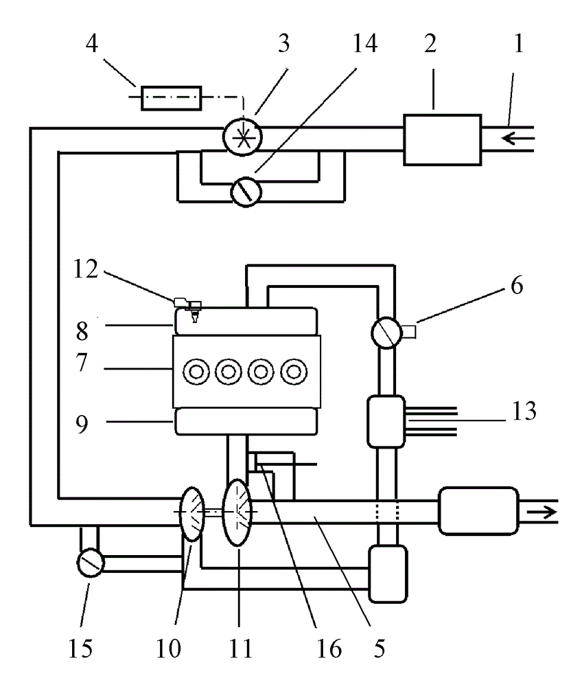
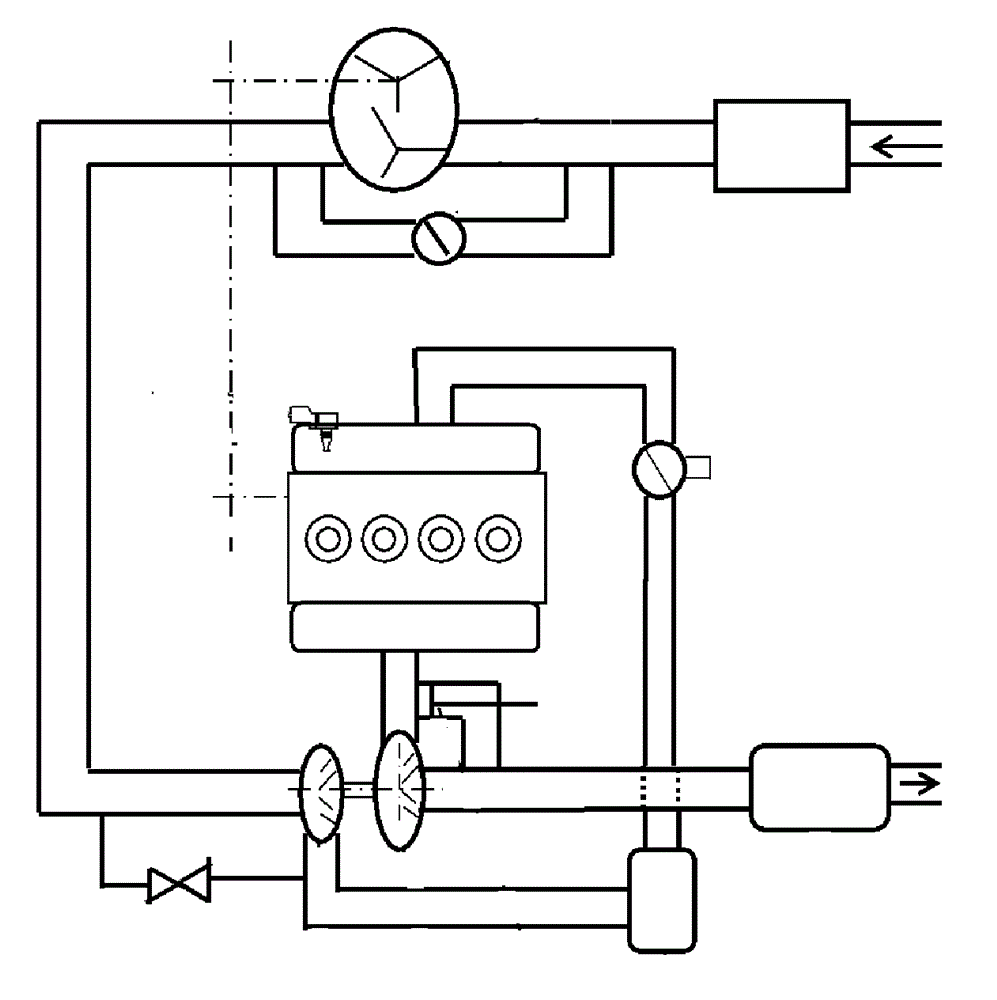
[0032] Please refer to figure 2 , which schematically shows the basic structure of an embodiment of the engine air intake system. The engine intake system is composed of an intake pipe 1, a filter 2, a first turbocharger 3, a load d...


PUM


Abstract

The invention relates to an engine air intake system. The engine air intake system comprises an air intake pipe and an air exhaust pipe, the two of which keep in air communication with a cylinder of an engine, and further comprises a filter, a first turbocharger, a loading device, a throttle valve and an engine controller. The filter is arranged in an inlet of the air intake pipe; the first turbocharger is arranged on the air intake pipe; the loading device is electrically connected with the first turbocharger; the throttle valve is arranged on the air intake pipe, and is used for adjusting the flow of air entering the cylinder of the engine; the engine controller keeps communicating with the loading device and the throttle valve; and when the rotating speed of the engine exceeds a first rotating speed value, the engine controller commands the loading device to drive the first turbocharger to operate. The invention further relates to a vehicle provided with the engine air intake system. The engine air intake system has such advantages as compact arrangement and good supercharging effect.

Description

technical field [0001] The invention relates to an engine air intake system, and also relates to an automobile provided with the engine air intake system, which belongs to the field of automobile engines. Background technique [0002] With the improvement of fuel economy requirements and emission requirements, in-cylinder direct injection and dual variable camshaft control are gradually applied to gasoline engines, and small displacement engines are gradually becoming mainstream engines. In order to maintain greater power and torque , Most of the small-displacement engines use the intake system with supercharging technology. [0003] Commonly used supercharging systems include mechanical supercharging systems, single exhaust gas turbocharging systems, twin turbocharging systems, and dual supercharging systems that combine supercharging and exhaust gas turbocharging. Most of the cooling systems of these systems use a first-stage air-cooling system with limited cooling effect...

Claims


Application Information

Patent Timeline
Patent Type & Authority Applications(China)
IPC IPC(8): F02B37/04F02M35/10
CPCY02T10/12
Inventor 朱小慧何小明何默郭敬爱
Owner SAIC GENERAL MOTORS
Why Eureka
Try Eureka