
Gain recycling system of liquefied natural gas (LNG) cold energy

A technology of liquefied natural gas and cold energy, which is applied in fixed-capacity gas storage tanks, container discharge methods, gas/liquid distribution and storage, etc., can solve the problems of difficult cold energy comprehensive recovery and utilization schemes put into practice, low recovery efficiency, poor economy

Inactive Publication Date: 2015-05-06
深圳市开迩文科技有限公司
View PDF10 Cites 3 Cited by
  • Summary
  • Abstract
  • Description
  • Claims
  • Application Information

AI Technical Summary

Problems solved by technology

However, since the recovery efficiency of work is still relatively low, it is acceptable to use it as an auxiliary power for large-scale natural gas gas-fired power plants. If the LNG cold energy power recovery power station is built separately, its economic efficiency is poor; It is more complicated, and it is necessary to configure the cooling transmission system and the power-driven power generation system separately, and the engineering feasibility is poor
In addition, most importantly, since the cold energy utilization of LNG is closely related to the consumption of LNG, only when LNG is consumed stably for a long time, the cold energy utilization system can run stably. Although the system is relatively complicated, the energy utilization efficiency is also high. Relatively high
However, the actual situation is that the large fluctuations in LNG consumption (such as LNG peak-shaving stations, LNG satellite stations, LNG-fueled vehicles, ships, etc.), and the consideration of the safety around the LNG vaporization station, it is difficult to efficiently The comprehensive recovery and utilization of cold energy is put into practice; on the other hand, for the occasions where the consumption of LNG is relatively small, it is not suitable for power recovery

Method used


Image

  • Gain recycling system of liquefied natural gas (LNG) cold energy

Examples


Embodiment Construction

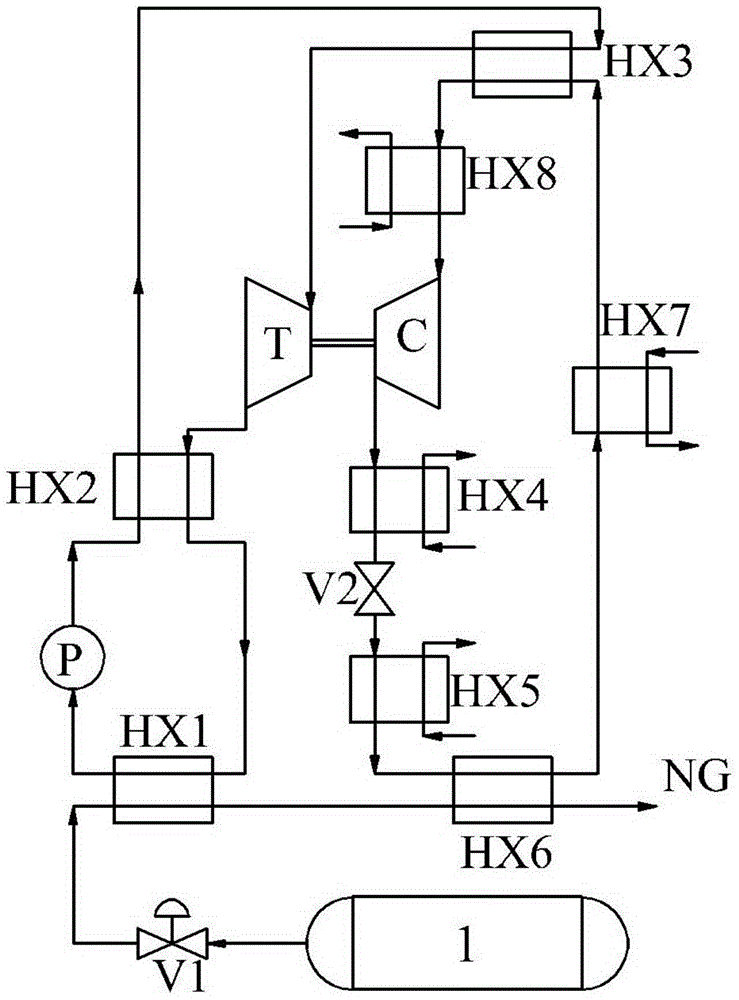
[0014] The present invention will be described in further detail below in conjunction with the accompanying drawings.

[0015] Referring to the accompanying drawings, a gain recovery system for liquefied natural gas cooling capacity includes an LNG fuel tank 1, the outlet of the LNG fuel tank 1 is connected to the inlet of the flow control valve V1 through a high-vacuum heat-insulated pipe, and the outlet of the flow control valve V1 is passed through The high vacuum insulation tube is connected to the cold fluid inlet of the LNG vaporizer HX1, the cold fluid outlet of the LNG vaporizer HX1 is connected to the cold fluid inlet of the low-temperature natural gas reheating heat exchanger HX6, and the cold fluid outlet of the low-temperature natural gas reheating heat exchanger HX6 passes through the gas The reheating pipeline is connected to the inlet of the downstream natural gas supply pipeline;

[0016] The hot fluid outlet of the LNG vaporizer HX1 is connected to the P inlet...


PUM


Abstract

The invention relates to a gain recycling system of liquefied natural gas (LNG) cold energy. Heat is absorbed from a refrigeration space and is used for vaporizing low-temperature LNG and a power cycle is constructed between a refrigerant temperature and an LNG temperature, and output power is used for driving a compression refrigeration system and producing cold energy; the gain output of LNG cold energy is achieved by the three-time liquefaction and three-time evaporation of a low-pressure and low-temperature refrigerant steam in the compression refrigeration system and three parts of cold energies are respectively derived from cold energy released from the vaporization process of LNG, cold energy released from rewarming process of low-temperature LNG and cold energy output by the compression refrigeration cycle driven by the power cycle which is driven by the temperature difference between LNG and the refrigeration space. The gain recycling system is applicable to application occasions which are smaller in LNG consumption scale and not suitable for comprehensive recycling of power and cold energy and has flow fluctuations, the cold energy is used as only energy output form for recovering energy, and the gain recycling system has the advantages of very strong feasibility and high efficiency and has good potential for industrialization promotion.

Description

technical field [0001] The invention belongs to the technical field of refrigeration and energy saving, and relates to a gain recycling system of liquefied natural gas cold capacity. Background technique [0002] Liquefied natural gas (LNG) is a low-temperature fuel stored at -162°C under atmospheric pressure. Its density is more than 600 times that of natural gas under standard conditions. The energy storage density is greatly improved, which greatly reduces the transportation cost of long-distance natural gas trade (such as ocean trade). In addition, since the raw natural gas has been subjected to pretreatments such as dust removal, purification, desulfurization, and deacidification during the production process of LNG, its combustion emission performance is much better than that of coal and oil. [0003] LNG is a low-temperature fuel. Before being burned, it needs to be vaporized and returned to normal temperature. During this period, about 890kJ / kg of cold energy will be...

Claims


Application Information

Patent Timeline
IPC IPC(8): F17C7/04F17C13/02
Inventor 谭宏博孙楠楠厉彦忠
Owner 深圳市开迩文科技有限公司
Learn More