Photosensitive resistance encoder based on mechanical subdivision and measuring method thereof

A technology of photoresistors and encoders, applied in the field of encoders, can solve the problems of complex manufacturing process of code discs, inability to meet ultra-high resolution processing and production, and encoder resolution limited by code discs, etc.

Active Publication Date: 2015-05-06
嘉兴笼列电子商务有限公司
View PDF6 Cites 6 Cited by
  • Summary
  • Abstract
  • Description
  • Claims
  • Application Information

AI Technical Summary

Problems solved by technology

Although this kind of encoder is simple in principle, reliable in operation and strong in anti-interference, the manufacturing process of the code disc is complicated, and the maximum number of code tracks and lines that can be engraved is also limited to a certain extent, which cannot meet the needs of ultra-high resolution processing and production. requirements
[0005] Chinese patent CN200710006964.7 discloses an encoder, the encoder is installed on a motor or a machine driven by a motor, and the encoder that detects position information or speed information can express various internal reasons and external reasons. Or the time-dependent change information of the encoder signal characteristic value caused by a long time, so as to obtain valuable information for fault prediction and to determine the cause of intermittent alarms, thereby improving the maintainability of the encoder; This technical solution mainly processes the signal output by the traditional encoder to improve the encoding effect, but it does not solve the technical problem that the resolution of the existing encoder is limited by the code disc

Method used


Image

  • Photosensitive resistance encoder based on mechanical subdivision and measuring method thereof
  • Photosensitive resistance encoder based on mechanical subdivision and measuring method thereof
  • Photosensitive resistance encoder based on mechanical subdivision and measuring method thereof

Examples


Embodiment 1

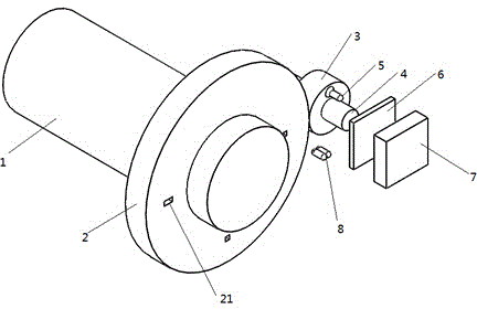
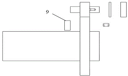
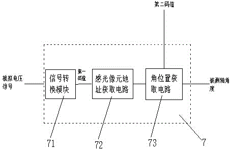
[0038] Such as Figure 1-2 As shown, it is a structural schematic diagram of a photoresistive encoder based on mechanical subdivision in this embodiment, including a main shaft 1, and the main shaft 1 is fixed with a driving wheel 2, and the driving wheel 2 is distributed with a plurality of small holes 21, and the driven wheel 3 Cooperate with the driving wheel 2 to install and connect, and the driving wheel 2 drives the driven wheel 3 to rotate. In this embodiment, the transmission ratio between the driving wheel 2 and the driven wheel 3 is 4, and the driven wheel 3 is fixed on the driven shaft 4, so The first laser source 5 is fixed on the driven wheel 3, the laser source is a single-beam laser source, the photoresistor array 6 is located in front of the first laser source 5, and the area array signal processing system 7 is connected with the photoresistor array 6-phase connection, such as image 3 As shown, the area array signal processing system 7 includes a signal conve...

Embodiment 2

[0041] This embodiment is a measurement method based on a mechanically subdivided photoresistive encoder of the present invention, which specifically includes the following steps:

[0042] S1. Connect the main shaft of the encoder to the rotating shaft to be measured through a coupling, the main shaft and the rotating shaft perform synchronous rotation, and at the same time the first and second laser light sources are energized to emit laser light;

[0043] S2. After receiving the laser signal, the photosensitive element in the photoresistor area array and the laser receiving module converts the laser signal into an analog voltage signal, and outputs the analog voltage signal;

[0044] S3. The signal conversion module in the area array signal processing system converts the analog voltage signal output by the photoresistor area array in step S2 into a data signal 1 or 0 to form a first code value, and the photosensitive pixel address acquisition circuit according to the first co...

Embodiment 3

[0056] This embodiment will combine the encoder in the first embodiment and the measurement method in the second embodiment;

[0057] In this embodiment, for the convenience of explanation, the photoresistor area array is composed of 4 coms photosensitive elements (there are many elements in the actual system), the code value of the driving wheel is composed of two code tracks (small holes), and the driving wheel and the slave The transmission ratio of the driving wheel is equal to the binary value of the code value (in this example, the binary value of the code value of the two code tracks is 4, then the transmission ratio is 4, and the subdivision multiple of the main shaft measurement is also 4), the measurement method in the second embodiment is adopted , then when the first laser source irradiates a photosensitive element on the photoresistor array, the photosensitive element will output a digital signal 1, and the rest of the photosensitive elements will output a digi...


PUM


Abstract

The invention discloses a photosensitive resistance encoder based on mechanical subdivision, belonging to the field of an encoder; the photosensitive resistance encoder comprises a spindle; a driving wheel is fixed on the spindle; a driven wheel is equipped and connected with the driving wheel in a matching manner; the driven wheel is fixedly installed on a driven shaft and fixedly provided with a first laser source; a photosensitive resistance area array is located in front of the first laser source; an area array signal processing is connected with the photosensitive resistance area array; a second laser source is located in front of the driven wheel; and a driving wheel code value processing system is located behind the driving wheel. The invention further discloses a measuring method for the encoder. The encoding resolution ratio of the photosensitive resistance area array is subdivided in a mechanical transmission manner; the problem of high cost caused by too large size of the photosensitive resistance area array is solved, and meanwhile, the technical difficulty of the resolution ratio of the present encoder limited by a coded disc is also solved; and the resolution ratio of the encoder is improved greatly.

Description

technical field [0001] The invention relates to the field of encoders, in particular to a photosensitive resistance encoder based on mechanical subdivision and a measuring method thereof. Background technique [0002] In the production of modern manufacturing industry, higher and higher requirements are put forward for the precision of mechanical operation. The encoder is a key device that affects the accuracy of the mechanical operation. It feeds back the shaft position information to the control system during the movement of the mechanical shaft to achieve the purpose of accurately controlling the position and speed of the rotary motion of the shaft. [0003] There are two types of encoders: absolute and relative. The absolute encoder can reflect the position information of the mechanical shaft relative to the predetermined origin, while the relative encoder reflects the position information of the current axis relative to the previous axis. [0004] At present, many a...

Claims


Application Information

Patent Timeline
Patent Type & Authority Applications(China)
IPC IPC(8): G01D5/26G01B11/26
Inventor 王新力
Owner 嘉兴笼列电子商务有限公司
Why Eureka
Try Eureka