Internal combustion engine control device and method

A control device and control method technology, applied in engine control, internal combustion piston engine, valve device, etc., can solve the problems of small response delay of variable compressor mechanism and easy knocking

Inactive Publication Date: 2015-05-06
HITACHI AUTOMOTIVE SYST LTD
View PDF4 Cites 8 Cited by
  • Summary
  • Abstract
  • Description
  • Claims
  • Application Information

AI Technical Summary

Problems solved by technology

[0003] Here, when the deceleration operation transitions from a high-load state to a low-load state, the response delay of the variable compressor mechanism to change the compression ratio is smaller than the response delay of the decrease in the intake air amount, so it becomes the pressure of the intake air. In a state of high compression and an excessive amount of intake air, knocking, etc. are prone to occur

Method used


Image

  • Internal combustion engine control device and method
  • Internal combustion engine control device and method
  • Internal combustion engine control device and method

Examples


Embodiment Construction

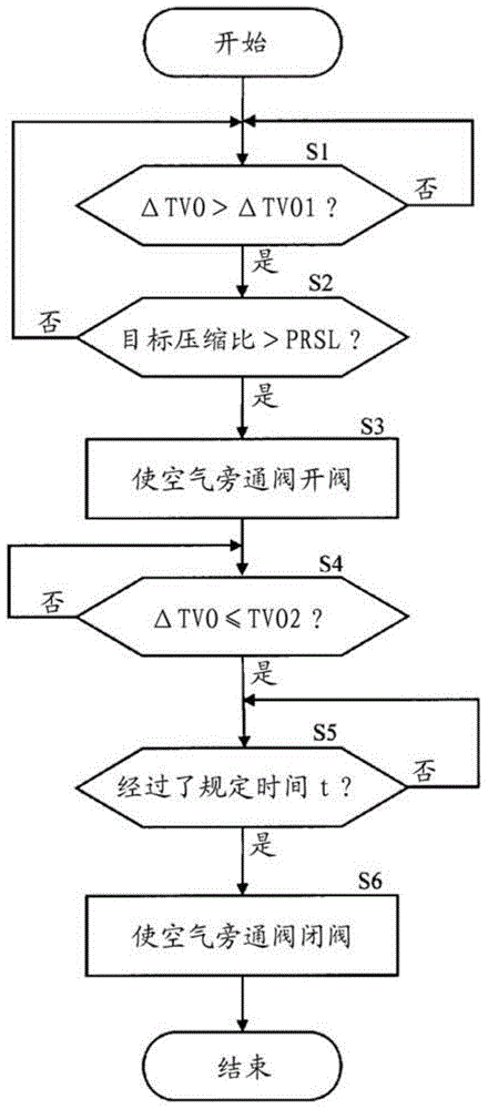
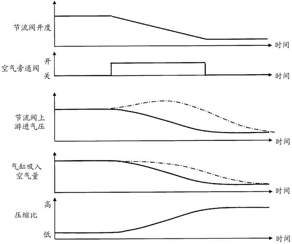
[0022] Embodiments of the present invention will be described below with reference to the drawings.

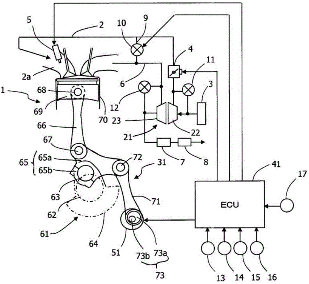
[0023] figure 1 The outline of the engine system of the first embodiment is shown.

[0024] On the intake passage 2 of the engine (internal combustion engine) 1, an air cleaner 3, a compressor 22 of an exhaust turbocharger 21, an electronically controlled throttle valve 4 for adjusting the amount of intake air are mounted from the upstream side, and A fuel injection valve 5 is attached to the intake port 2a portion.

[0025] In the exhaust passage 6, a turbine 23 of an exhaust turbocharger 21, an exhaust purification catalytic device 7 for purifying exhaust gas, and a muffler 8 are attached from the upstream side.

[0026] In addition, an EGR passage 9 connecting the exhaust passage 6 between the engine 1 and the exhaust purification catalytic device 7 and the intake passage 2 downstream of the throttle valve 4 is arranged, and an EGR control device for adjusting the amount ...


PUM


Abstract

Provided is an internal combustion engine having a variable compression ratio mechanism, wherein the occurrence of knocking during deceleration is suppressed. When it is determined that a target compression ratio of the variable compression ratio mechanism is at least a threshold PRSL during deceleration, an air bypass valve that is interposed in a channel that bypasses the compressor of an exhaust turbo charger is opened. Intake air from the throttle valve upstream region (between a compressor and a throttle valve) is returned to the compressor upstream region thereby reducing the intake air pressure in the throttle valve upstream region, and by reducing compression pressure in a cylinder, the occurrence of knocking is suppressed.

Description

technical field [0001] The invention relates to a control device and method of an internal combustion engine with a variable compression ratio mechanism. Background technique [0002] In order to improve the fuel economy of the internal combustion engine, a variable compression ratio mechanism for varying the compression ratio has been developed. In an internal combustion engine having a variable compression ratio mechanism, generally, knocking and pre-ignition (knock, etc.) are avoided by achieving a low compression ratio in a high-load region, and high compression ratio is achieved in a low-load region to improve fuel economy. [0003] Here, when the deceleration operation transitions from a high-load state to a low-load state, the response delay of the variable compressor mechanism to change the compression ratio is smaller than the response delay of the decrease in the intake air amount, so it becomes the pressure of the intake air. In a state of high compression and an...

Claims


Application Information

Patent Timeline
Patent Type & Authority Applications(China)
IPC IPC(8): F02D15/02F02D23/00F02B27/02
CPCF01L13/08F02B27/0215F02B27/0273F02B37/16F02D15/02F02D23/00F02D41/0005F02D41/0007F02M26/05Y02T10/12Y02T10/40F02D13/0234F02D23/02
Inventor 仓岛芳国
Owner HITACHI AUTOMOTIVE SYST LTD
Why Eureka
Try Eureka