
Stirrup box capable of compressing and orderly releasing spiral continuous stirrups

A technology of stirrup boxes and stirrups, applied in the field of stirrup boxes, can solve the problems of single steel bar skeleton style, and achieve the effects of saving molding time, improving work efficiency, and simple and reasonable structure

Inactive Publication Date: 2015-05-13
SHANDONG JIANZHU UNIV
View PDF8 Cites 7 Cited by
  • Summary
  • Abstract
  • Description
  • Claims
  • Application Information

AI Technical Summary

Problems solved by technology

[0003] The production process of the spiral stirrup directly affects the quality and production efficiency of the steel skeleton. When the existing steel skeleton seam welding machine makes the steel skeleton, it needs to weld the spiral stirrup while winding the spiral stirrup. If the spiral stirrup is pre-processed into a compressed "spring-like "It saves the time for forming the steel frame; the existing steel frame seam welding machine has a single style of steel frame, which can only surround the outer circumference of the main reinforcement. If the spiral stirrup is pre-processed into a spiral shape, the stirrup is put on the main reinforcement first and then inserted. The method can produce a steel frame with spiral stirrups in a staggered network structure, so this requires special steel frame forming equipment. The key part of this equipment is the matching stirrup storage and release device, which arranges the stirrups in an orderly manner. Distributed on the main reinforcement, improve the efficiency and quality of steel skeleton forming

Method used


Image

  • Stirrup box capable of compressing and orderly releasing spiral continuous stirrups
  • Stirrup box capable of compressing and orderly releasing spiral continuous stirrups
  • Stirrup box capable of compressing and orderly releasing spiral continuous stirrups

Examples


Embodiment Construction

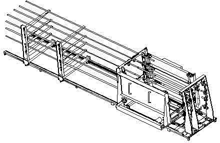
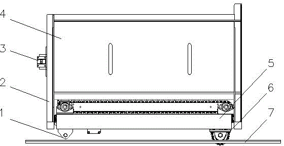
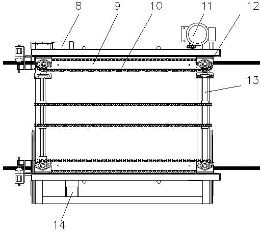
[0033] Such as figure 1 As shown, the stirrup box of the present invention, which can store and release spiral continuous stirrups in an orderly manner, is a key component of the steel skeleton forming machine. Such as figure 2 , image 3 , Figure 4 As shown, the stirrup box of the present invention includes a luffing device for adjusting the cross-sectional size of the stirrup box, a walking device for moving the stirrup box along the direction of the longitudinal bars, and a release device for storing and orderly releasing spiral continuous stirrups. Rib device. Wherein, the luffing device includes a chain transmission mechanism and a screw mechanism, and the sprocket of the chain transmission mechanism is coaxially connected with the lead screw 15 of the screw mechanism; The stirrup box moves as a whole; the tendon releasing device includes a chain transmission mechanism, the sprocket shaft 13 is arranged vertically and horizontally, the transmission direction of th...


PUM


Abstract

The invention discloses a stirrup box capable of compressing and orderly releasing spiral continuous stirrups. The stirrup box comprises a luffing device used for adjusting the size of the cross section of the stirrup box, a running device enabling the stirrup box to move in the longitudinal stirrup direction and a stirrup releasing device used for compressing, storing and orderly releasing the spiral continuous stirrups. The luffing device comprises a chain transmission mechanism and a screw mechanism. Chain wheels of the chain transmission mechanism are coaxially connected with a screw of the screw mechanism. The running device comprises a gear transmission mechanism, and a gear pair is arranged on the lower portion of the stirrup box to enable the stirrup box to move wholly. The stirrup releasing device comprises a chain transmission device, the chain wheels are arranged vertically and horizontally, the transmission direction of chains is identical, the stirrups are stored in space formed by the chains, and the chains support and transmit the stirrups. After the luffing device is adjusted according to the transverse sizes of the stirrups, the stirrup releasing device and the running device coordinate actions to complete releasing and arranging of the stirrups. The stirrup box can save molding time of a framework of a steel reinforcement, and reduce the entire size of equipment of the framework of the steel reinforcement.

Description

technical field [0001] The invention belongs to the technical field of steel frame forming construction in the construction industry, in particular to a stirrup box of a steel frame forming machine which can compress and release spiral continuous stirrups in an orderly manner. Background technique [0002] In the existing construction industry, a special roll welding machine is used to weld the circular cross-section steel frame to weld multiple circular main bars and spiral stirrups wound on the main bar. When the steel bar frame is formed, a driving system is required to drive the main bar as a whole and the existing ones. The formed skeleton rotates relative to the traction system to realize the winding of the stirrups on the main reinforcement. This forming method improves the mechanization level of steel skeleton forming to a certain extent, but there is still a gap with the energy-saving and environmentally friendly production process advocated by the country. At prese...

Claims


Application Information

Patent Timeline
IPC IPC(8): B21F27/00
Inventor 张明勤马荣全孟宪举苗冬梅原政军姚玉善王晴刘昆王凯靳斐郝圣文张旭
Owner SHANDONG JIANZHU UNIV
Learn More