
A kind of box girder welding method

A welding method and technology for box beams, which are applied in welding equipment, welding/welding/cutting items, resistance welding equipment, etc., can solve the problems of low efficiency and poor welding quality of wide-flange box beams, and solve the problems of welding quality poor, the effect of improving welding strength and welding work efficiency

Active Publication Date: 2017-01-25
HENAN MINE CRANE +1
View PDF7 Cites 0 Cited by
  • Summary
  • Abstract
  • Description
  • Claims
  • Application Information

AI Technical Summary

Problems solved by technology

[0010] The purpose of the present invention is to provide a box girder welding method, aiming to solve the problems of poor welding quality and low efficiency of wide flange box girder in the prior art

Method used


Image

  • A kind of box girder welding method
  • A kind of box girder welding method
  • A kind of box girder welding method

Examples


Embodiment Construction

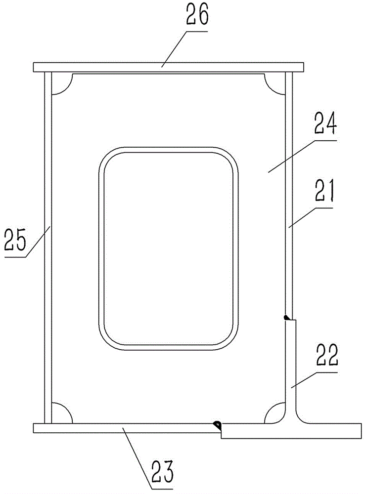
[0031] The embodiment of box girder welding method among the present invention: as Figure 6 to Figure 10 As shown, the method is a wide-flange box girder welding process consisting of the following steps:

[0032] 1. Fix the T-shaped steel 22 and the main web 21 by spot welding. The lower edge of the main web 21 is butt-welded and fixed on the edge of the vertical wall of the T-shaped steel 22, and then the T-shaped steel 22 and the main web 21 are welded by submerged arc welding. Flat welds with straight extension;

[0033] 2. Fix the T-shaped steel 22 and the upper cover plate 23 by spot welding. The right edge of the upper cover plate 23 is butt-welded and fixed on the left flange edge of the T-shaped steel 22, and then the T-shaped steel 22 and the upper cover plate 23 are welded by submerged arc welding. Flat welds extending in straight lines to obtain L-shaped half-beam workpieces;

[0034] 3. Fix the half-beam workpiece and the rib plate 24 by spot welding, place eac...


PUM


Abstract

The invention discloses a box beam welding method. The method comprises the steps that a main web and an upper cover plate are fixed to each other in a butt spot welding mode directly or through structural steel indirectly, all ribbed plates are arranged at intervals in the length direction of a semi-beam work piece formed by the welding of the main web and the upper cover plate, and the ribbed plates are fixed to the concave surface of the semi-beam work piece in a butt spot welding mode. Compared with the prior art that the welding of the upper cover plate and the main web is achieved in space in sections formed by the dividing by the ribbed plates, the welding of the upper cover plate and the main web is completed at a time in open space according to the box beam welding method. Accordingly, the welding strength between the main web and the upper cover plate of a box beam and the welding working efficiency are improved, and the problem existing in the prior art that the welding quality and the welding efficiency of the wide flange box beam are low is solved.

Description

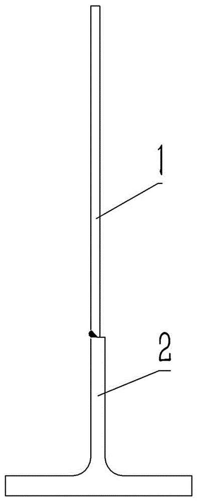
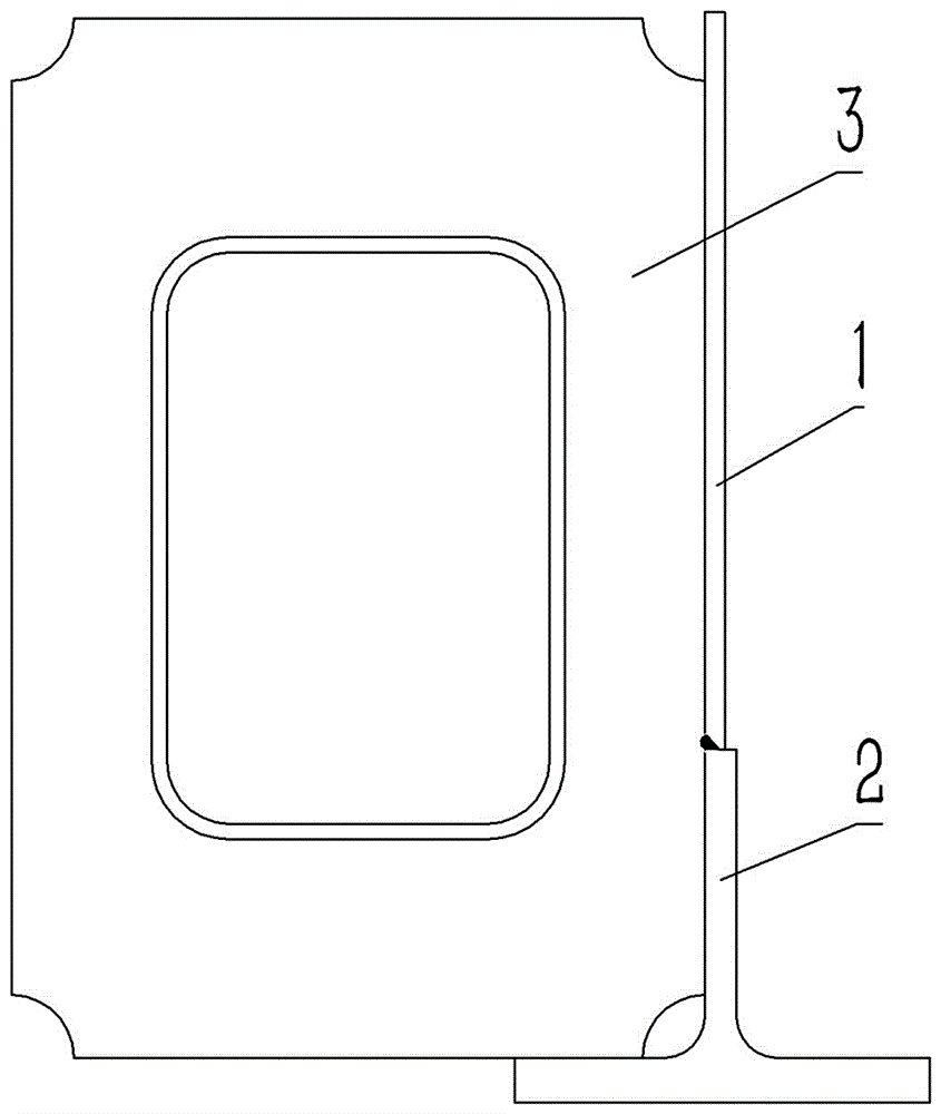
technical field [0001] The invention relates to a box girder welding method. Background technique [0002] As more and more production tasks in casting, metallurgy and other occasions require the use of wide-flange box girder cranes, compared with double-girder cranes with ordinary box girder structures, the manufacturing process of wide-flange box girder cranes There is a big difference in the process. The girder of the ordinary box structure is mainly composed of a web, a cover plate and a rib plate. The welding process is: first weld the rib plate and the upper cover plate, and then assemble the two web plates, weld the rib plate and the web plate, then assemble the lower cover plate, and weld the four large seams of the main beam. The welding process of wide flange box girder crane is as follows Figure 1 to Figure 5 shown, including the following steps: [0003] 1. Fix the T-shaped steel 2 and the main web 1 by spot welding, and then use submerged arc welding to weld ...

Claims


Application Information

Patent Timeline
Patent Type & Authority Patents(China)
IPC IPC(8): B23K11/11B23K11/36
CPCB23K9/0026B23K9/18B23K9/235B23K2101/28B23K2103/04
Inventor 杨昀
Owner HENAN MINE CRANE
Learn More