
Dual Rotary Drive

A driving device and double-rotation technology, which is applied in the direction of driving devices, large fixed members, machine tool parts, etc., to achieve the effect of high processing flexibility and large processing space

Active Publication Date: 2017-12-08
IND TECH RES INST
View PDF13 Cites 0 Cited by
  • Summary
  • Abstract
  • Description
  • Claims
  • Application Information

AI Technical Summary

Problems solved by technology

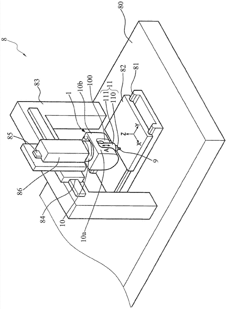
[0010] However, in the design of the existing drive structure (i.e., China Taiwan Patent Publication No. 201204506), the planetary gear reduction mechanism is in operation due to the backlash between the meshing teeth of the planetary gear, sun gear and ring gear affect the shaft unit 11 (eg figure 1 Shown) Positioning accuracy (Positioning accuracy) and repeatability accuracy (repeatability accuracy)

Method used


Image

  • Dual Rotary Drive
  • Dual Rotary Drive
  • Dual Rotary Drive

Examples


Embodiment Construction

[0073] The implementation of the present invention is described below through specific specific examples, and those skilled in the art can easily understand other advantages and effects of the present invention from the content disclosed in this specification.

[0074] It should be noted that the structures, proportions, sizes, etc. shown in the drawings attached to this specification are only used to match the content disclosed in the specification for the understanding and reading of those familiar with this technology, and are not used to limit the implementation of the present invention. Therefore, it has no technical substantive meaning. Any modification of structure, change of proportional relationship or adjustment of size shall still fall within the scope of this invention without affecting the effect and purpose of the present invention. The technical content disclosed by the invention must be within the scope covered. At the same time, terms such as "upper", "top", "...


PUM


Abstract

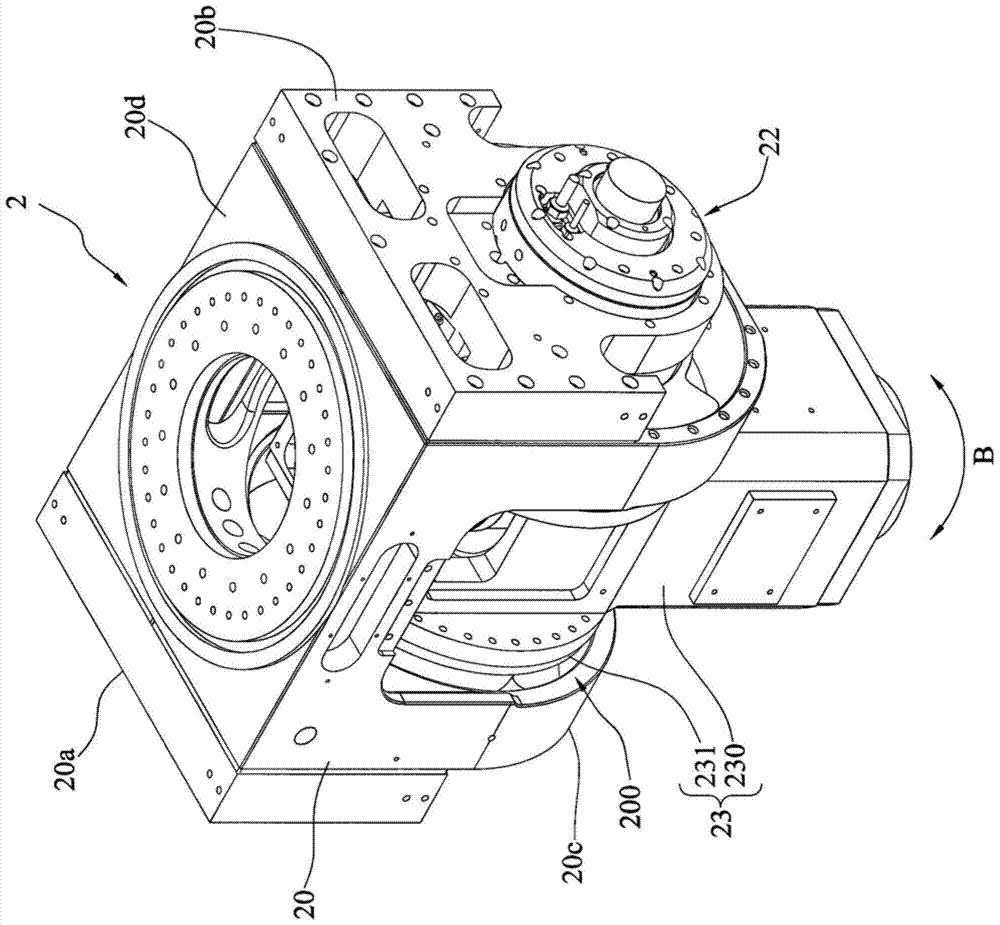
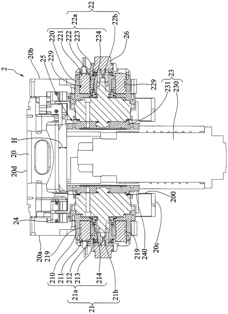
The invention discloses a dual-rotation driving device, which comprises: a base body; a shaft unit pivotally connected to the base body to carry workpieces; a first and a second drive unit arranged on the base body; the first and second drive units Each has a motor and a gear set, each of the motors is coaxially connected with each of the gear sets, and each of the gear sets is connected with the shaft unit. Through the design of two motors and two gear sets, the present invention can generate larger torque with smaller motors and smaller volume.

Description

technical field [0001] The present invention relates to a rotatable machine, in particular to a double rotary drive device for configuring a rotating body. Background technique [0002] Due to the significant increase in the computing speed of the computer numerical control (computer numerical control, CNC) controller of today's machine tools, coupled with computer-aided design (computer-aided design, CAD) and computer-aided manufacturing (computer-aided manufacturing, CAM) Software technology is constantly evolving, thus allowing multi-axis machining technology to flourish. [0003] figure 1 It is a three-dimensional schematic diagram of the existing multi-axis processing equipment 8 . The processing equipment 8 is provided with a first slide rail group 81 on a machine table 80, and a worktable 82 is provided on the first slide rail group 81, and the worktable 82 is used for setting the workpiece to be processed (not shown). A frame body 83 is erected on the machine tabl...

Claims


Application Information

Patent Timeline
Patent Type & Authority Patents(China)
IPC IPC(8): B23Q5/00
CPCB23Q5/00B25J9/102B25J17/0258B25J19/0054B23Q1/5406B23Q5/10B23Q5/56B23Q2220/006Y10S901/25Y10T74/20329
Inventor 吴进发许晋谋萧锡鸿李秋红
Owner IND TECH RES INST
Learn More