
Construction method of flexible arch bridge with rigid beams

A construction method and beam flexibility technology, applied in the construction field of rigid beam flexible arch bridges, can solve the problems of increasing the burden of arch ribs and beams, increasing the project cost, and the lifting height of cranes, etc., so as to improve the integrity and stability, reduce the Small construction cost and the effect of improving economic efficiency

Active Publication Date: 2015-05-13
CHINA MAJOR BRIDGE ENERGINEERING
View PDF10 Cites 22 Cited by
  • Summary
  • Abstract
  • Description
  • Claims
  • Application Information

AI Technical Summary

Problems solved by technology

The main span of the dedicated channel bridge of the Hutong Yangtze River Bridge is 336m. The upper layer is a 6-lane expressway and the lower layer is a four-line railway. The design live load is large and the design standard is high. The hoisting height of the crane is huge, and the installation cost of the arch is high; in addition, the boom is 60m long. Due to the requirement of slenderness ratio, the section size of the boom is large and the weight is heavy, which not only increases the burden on the arch ribs and beams, increases the project cost, but also increases Greater risk of wind-induced damage to the boom
If the rigid arch flexible beam and flexible suspender system are used, the construction and installation of the rigid arch are relatively complicated, resulting in high project cost

Method used


Image

  • Construction method of flexible arch bridge with rigid beams
  • Construction method of flexible arch bridge with rigid beams
  • Construction method of flexible arch bridge with rigid beams

Examples


Embodiment Construction

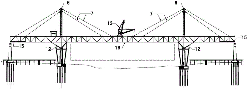
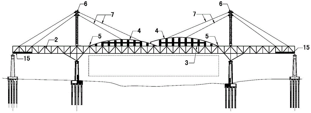
[0020] Below take two main pier, both sides pier as example to describe the present invention in detail with reference to accompanying drawing, Figure 1-Figure 6 Two bridge piers in the middle are main piers, and two bridge piers outside are side piers; Construction steps of the present invention:

[0021] 1) The middle steel truss girder 1 between the two main piers, the side steel truss girder 2 between the main pier and the side piers, the steel box arch 4 and the flexible suspender 8 are divided into individual components in the factory and fabricated in sections;

[0022] 2) Set up the pier side bracket 12 on the top of the main pier, use the floating crane to assemble the medium steel truss girders 1 between the four sections on the pier side bracket, install a 70t full-slewing girder crane 13 on the medium steel truss girder, lift rack 14 (see figure 1 );

[0023] 3) Assemble the sling tower 6 on the medium steel truss girder 1, continue to assemble the side steel t...


PUM


Abstract

The invention relates to a construction method of a flexible arch bridge with rigid beams. Steel truss beams, a steel box arch and flexible hanging rods are divided into single members in a factory and manufactured in a segmented mode; by the adoption of the symmetrical cantilever erection method, installation of the rigid steel truss main beam is completed firstly; then, an arch rib is installed, a crane travels on an upper bridge deck, the arch rib is divided into two half arches, welding forming is conducted on the two half arches on the upper bridge deck, the arch rib is vertically rotated in place through auxiliary facilities such as vertical rotating hinges, temporary sling towers and temporary inhaul cables between the arch rib and the steel truss beams, and middle span closing of the arch rib is achieved. After installation of the steel truss beams and the arch rib is completed, flexible slings are installed on the upper bridge deck and tensioned, and installation of the main structure is completed. By the adoption of the construction method that the steel truss beams are installed first and then the arch rib is installed, construction difficulty of the arch rib is reduced, the hoisting height of the crane is reduced, the construction period is greatly shortened, construction costs are lowered, economic benefits are increased, structural integrality and stability of the large-span arch bridge are enhanced in the construction process, and construction risk is reduced.

Description

technical field [0001] The invention relates to a construction method of a rigid beam flexible arch bridge. Background technique [0002] Different design and construction methods of long-span arch bridges directly affect the cost and construction period of the project. Reasonable construction technology can not only effectively shorten the construction period, but also bring considerable economic benefits. [0003] At present, there are two types of long-span arch bridges with double-deck decks: one is a combination system of rigid beams, flexible arches, and rigid suspenders. When installing arch ribs in this structure, the crane travels on the upper deck to fix the arch ribs. The other is a combination system of rigid arch flexible beams and flexible suspenders. When installing arch ribs in this structure, the crane walks on the truss arch to install arch ribs and suspenders. The main span of the dedicated channel bridge of the Hutong Yangtze River Bridge is 336m. The up...

Claims


Application Information

Patent Timeline
IPC IPC(8): E01D21/00E01D4/00
CPCE01D4/00E01D21/00
Inventor 高宗余徐伟肖海珠张燕飞彭振华鲍莉霞侯建付岚岚罗扣王恒郑清刚何东升刘厚军苑仁安张金涛徐力戴慧敏唐斌
Owner CHINA MAJOR BRIDGE ENERGINEERING
Learn More