

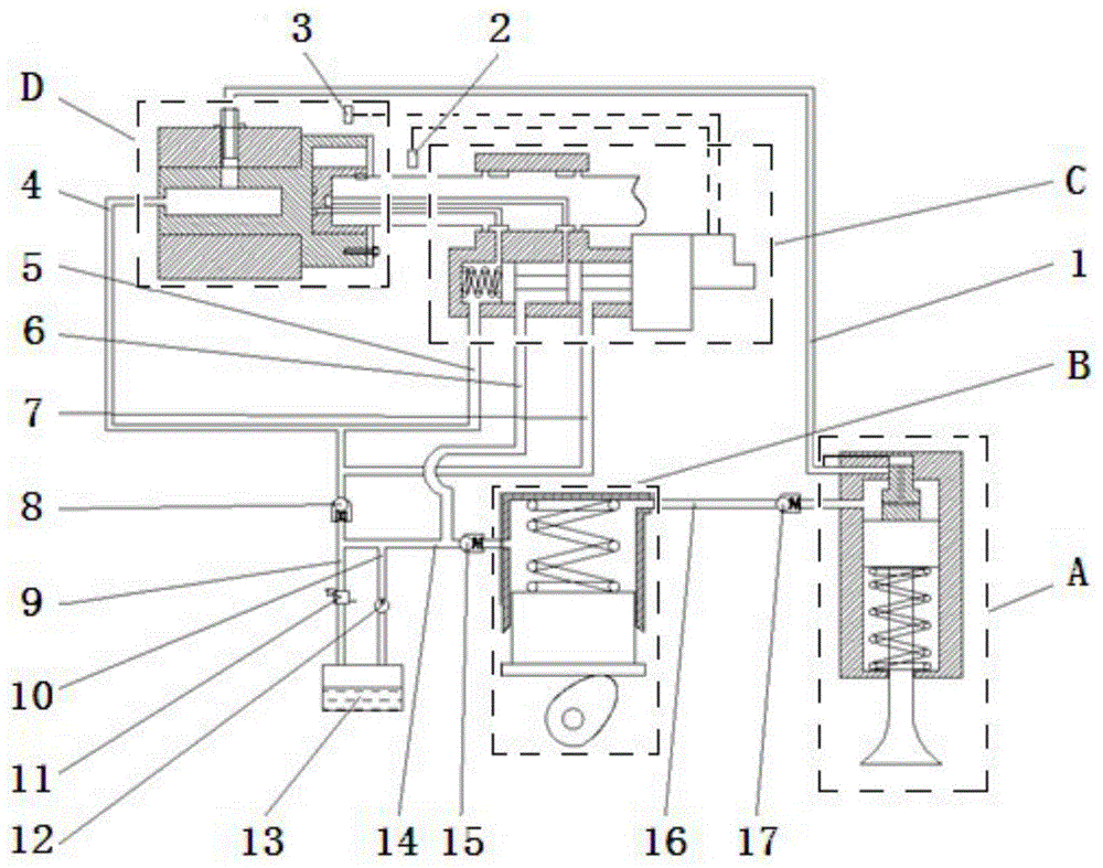
Gas intake and distribution system based on electric hydraulic control mode
An electro-hydraulic control and control mechanism technology, applied in engine control, valve details, valve drive devices, etc., can solve problems such as small variable range of gas distribution phase, complex transmission mechanism, energy consumption, etc., to avoid insufficient response speed, The effect of flexible lift control and low manufacturing cost
- Summary
- Abstract
- Description
- Claims
- Application Information
AI Technical Summary
Problems solved by technology
Method used
Image

Examples
Embodiment Construction
[0028] The concrete work process of the present invention is illustrated below in conjunction with accompanying drawing:
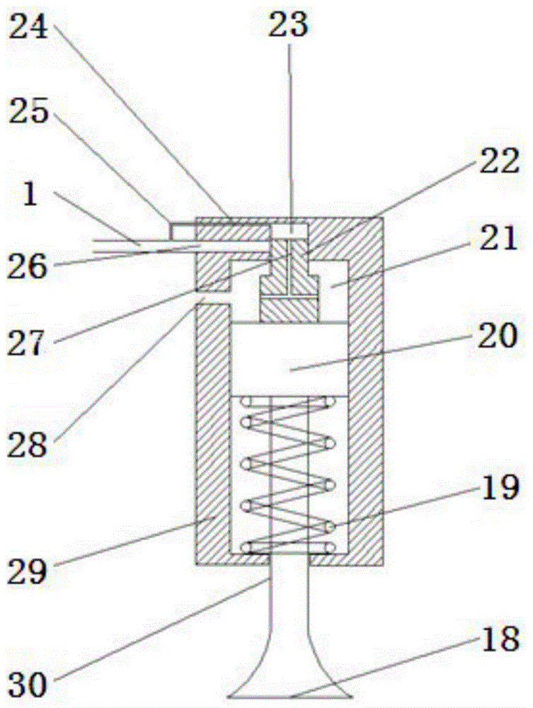
[0029] figure 2 It is a structural diagram of the valve drive mechanism A, including valve 18, valve spring 19, valve piston 20, piston chamber 21, valve buffer block 22, buffer chamber 23, buffer oil return hole 24, buffer oil inlet pipe 25, oil return hole I26, buffer block Oil hole 27, oil inlet hole I28, valve housing 29, and valve hole 30 are composed, wherein the bottom of valve housing 29 is provided with valve hole 30, and the upper left wall of valve housing 29 is provided with buffer oil return hole 24, The oil return hole I26 and the oil inlet hole I28, the valve housing 29 is provided with a buffer chamber 23; one end of the buffer oil inlet pipe 25 communicates with the buffer chamber 23 through the buffer oil return hole 24, and the other end of the buffer oil inlet pipe 25 communicates with the oil return pipe I1; The upper part of the val...
PUM
 Abstract
Description
Claims
Application Information