Tunnel pipeline monitoring and early warning system

An early warning system and technology in tunnels, which are used in measurement devices, heat measurement, liquid/fluid solid measurement, etc., can solve problems such as large inspection workload, large engineering volume, and difficulty in finding deformation of pipes and pipe clamps. Achieve the effect of improving the level and efficiency of pipeline management

Active Publication Date: 2015-05-13
CHINA PETROLEUM & CHEM CORP +1
View PDF11 Cites 30 Cited by
  • Summary
  • Abstract
  • Description
  • Claims
  • Application Information

AI Technical Summary

Problems solved by technology

The main problems of this manual inspection method are as follows: first, the tunnel space is relatively closed, and you must maintain good ventilation and lighting to enter. Some tunnels are several kilometers long, and the inspection workload is heavy and the safety risk is high; The deformation of the card and support is difficult to find through manual inspection; third, it is impossible to grasp the safety status of the pipeline and auxiliary facilities in the tunnel in real time, and it is often discovered and dealt with after the event; fourth, there may be water in the river tunnel. Drainage and ventilation operations require a huge amount of work. If the tunnel is filled with water after completion, the preparation work before the inspection will be even more difficult.
[0005] Among the disclosed existing technologies, there are technologies and methods such as deformation monitoring of the tunnel structure body, pipeline monitoring and early warning in unfavorable geological areas, and natural gas leakage monitoring in open space tunnels. There is no safety monitoring and early warning technology for pipelines in tunnels

Method used


Image

  • Tunnel pipeline monitoring and early warning system
  • Tunnel pipeline monitoring and early warning system
  • Tunnel pipeline monitoring and early warning system

Examples


example 1

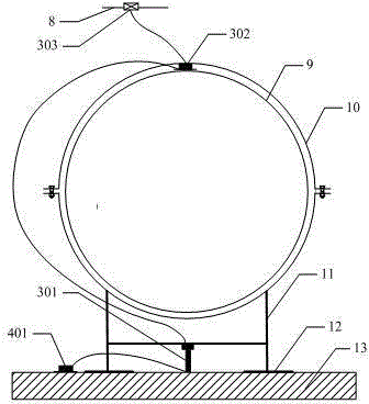
[0038] Example 1: Combining with Figure 5 The present invention is further described.

[0039] The example is an application example of the present invention in a shield tunnel in which a pipeline crosses a river.

[0040] The shield tunnel is a main way for pipelines to cross large rivers. Its structure is U-shaped and consists of tunnel shafts 15 on both sides of the river and tunnel tunnels 16 connecting the shafts. The tunnel entrance 14 is located at the top of the shaft 15. . Pipes 9 are laid in the tunnel, fixed by pipe clips 10 and installed on a series of bottom supports 11 . Therefore, the pipeline line also assumes a "U" shape in the tunnel. When the pipeline is put into operation, due to the change of the pressure and temperature of the conveying medium in the pipeline, stress will be generated inside the pipeline, which will lead to the expansion and contraction deformation of the pipeline. For the "U"-shaped line of the shield tunnel, the theoretical analysi...


PUM

PropertyMeasurementUnit
diameteraaaaaaaaaa

Abstract

The invention discloses a tunnel pipeline safety monitoring and early warning system. The monitoring system is composed of a pipeline deformation measurement unit, a temperature measurement unit, a support displacement and reaction force measurement unit, a water level detection unit, a field data acquiring and processing unit, a field acousto-optic alarm, a remote analysis and control terminal, and an optical cable. Monitoring signals of the measurement units are acquired and processed by a multi-channel demodulation module and a field analysis and processing module, and transmitted to the remote analysis and control terminal through a wireless transmission module by a GPRS protocol. A piece of control system software carries out statistical recording and early warning analysis of the monitoring signals, and performs safety threshold setting, monitoring system remote control, and field acousto-optic alarming. Due to the modular and multi-channel design of the monitoring system, different monitoring programs and multiple groups of monitoring points can be configured according to the monitoring need, the requirement of monitoring and early warning of mountain, river and other tunnel-through pipelines can be met, and automatic remote intelligent tunnel pipeline monitoring and management is realized.

Description

technical field [0001] The invention relates to a safety monitoring and early warning system for oil and gas pipelines in tunnels, in particular to on-line monitoring and safety warnings for oil and gas pipelines in tunnels crossing mountains and rivers, and belongs to the technical field of pipeline safety and measurement. Background technique [0002] my country's pipeline engineering is in a period of rapid development, and more and more pipelines have to pass through various geological topography areas. Among them, tunnels are a major way for pipelines to cross complex mountains and large rivers. Tunnels for pipelines generally have the characteristics of small cross-sectional area and various crossing routes. That is, the cross-sectional area of ​​the tunnel should be as small as possible to reduce the amount of excavation while meeting the needs of pipeline installation. The tunnel route can be flexibly designed according to the terrain and geological conditions. For e...

Claims


Application Information

Patent Timeline
Patent Type & Authority Applications(China)
IPC IPC(8): G01B11/16G01K11/32G01F23/00G01K11/3206
Inventor 王晓霖阮宗琳李明吕高峰陈天佐
Owner CHINA PETROLEUM & CHEM CORP
Why Eureka
Try Eureka