Reactive compensation configuration method

A configuration method and static var technology, applied in reactive power compensation, reactive power adjustment/elimination/compensation, circuit devices, etc., can solve problems such as fluctuations in power output of photovoltaic power station clusters

Inactive Publication Date: 2015-05-13
SOUTHEAST UNIV
View PDF3 Cites 14 Cited by
  • Summary
  • Abstract
  • Description
  • Claims
  • Application Information

AI Technical Summary

Problems solved by technology

After adding photovoltaic power generation, the research on the random probability of photovoltaic has been applied to the problem of reactive power compensation planning. How

Method used


Image

  • Reactive compensation configuration method
  • Reactive compensation configuration method
  • Reactive compensation configuration method

Examples


Embodiment Construction

[0031] The technical solution of the invention will be described in detail below in conjunction with the accompanying drawings.

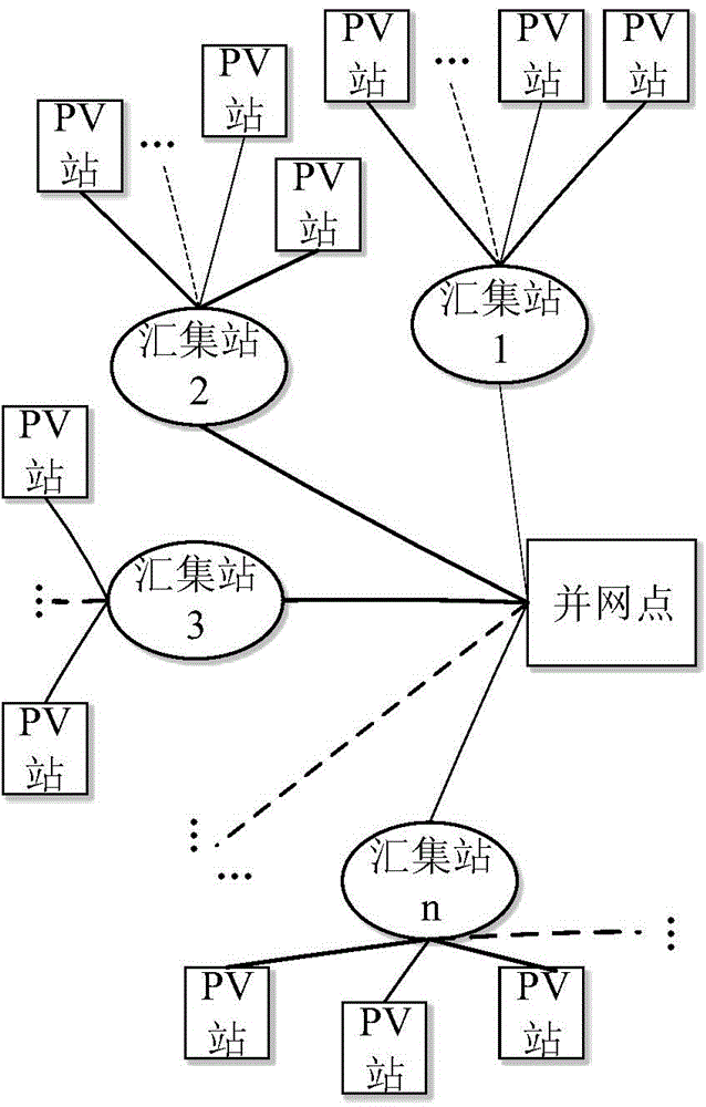
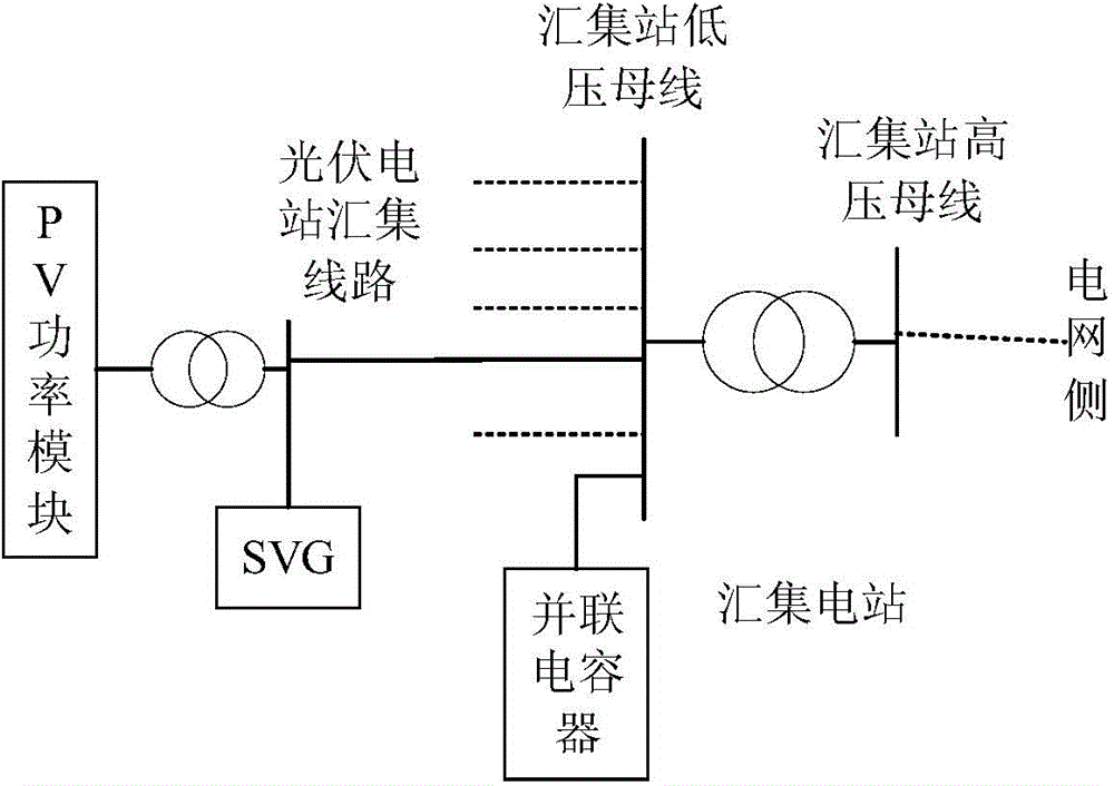
[0032] Schematic diagram of large-scale photovoltaic grid-connected structure see figure 1 . In order to realize the optimal compensation of such networks, shunt capacitors and static var generators (static var generator, SVG for short) are used for collaborative configuration compensation. Among them, the shunt capacitor is installed on the low-voltage side busbar of the collection substation of the power generation and transmission system, and the SVG is installed on the outlet busbar of the photovoltaic power station, such as figure 2 shown. A reactive power planning optimization method based on chance constraints is established. In this method, the configuration of shunt capacitors is realized through the chance constraints of the traditional grid structure, and the configuration of the photovoltaic power station SVG is realized through the c...


PUM


Abstract

The invention discloses a reactive compensation configuration method, in particular relates to an active optimizing method of a generation and transmission grid including probability fluctuation power connection, and belongs to the technical field of reactive optimization of power systems. The method comprises the steps of forming a node admittance matrix in the power system, and setting initial voltage of each node; selecting control variable and state variable; building a reactive optimization change limitation mathematical model which specially includes target functions, portability characteristic limiting conditions and fluctuation characteristics limitation conditions; determining the configuration of the control variable by the stochastic particle swarm optimization based on the latin hypercube probabilistic power flow. With the adoption of the method, a reactive compensation device in the transmission grid can be effectively configured according to the power probability characteristics and fluctuation characteristics of the grid connection of a large-scale photovoltaic station, and therefore, the grid can run normally based on the probability meanings, and moreover, the voltage fluctuation of the photovoltaic power can be greatly reduced, and as a result, the voltage and electricity energy quality of the grid can be increased.

Description

technical field [0001] The invention discloses a reactive power compensation configuration method, in particular relates to a reactive power optimization method for a power generation and transmission network with access to a probabilistic fluctuating power source, and belongs to the technical field of reactive power optimization of electric power systems. Background technique [0002] With the increasing consumption of fossil energy, traditional energy can no longer meet the demand for energy supply in the development of human society, and renewable energy has been increasingly accepted and developed by human beings. As an inexhaustible clean energy, solar energy has received deep research and attention, especially the traditional solar-thermal energy technology has been widely used in various aspects. As an energy method with high efficiency and flexibility in both utilization efficiency and usage form in the energy system, electric energy has become an indispensable daily...

Claims


Application Information

Patent Timeline
IPC IPC(8): H02J3/18
CPCH02J3/1871H02J3/1878H02J3/24H02J2203/20Y02B10/10Y02E10/56Y02E40/30
Inventor 高山刘宇于乐胡汉
Owner SOUTHEAST UNIV
Why Eureka
Try Eureka