Metal energy storage spring machining method

A technology of energy storage springs and processing methods, which is applied in the direction of springs, etc., can solve problems such as easy failure in use, failure to restore the end of the steel strip, failure to meet the requirements of design drawings, etc., and achieve the effects of easy repair, high yield, and reliable processing methods

Active Publication Date: 2015-05-20
HARBIN DONGAN IND DEV
View PDF7 Cites 2 Cited by
  • Summary
  • Abstract
  • Description
  • Claims
  • Application Information

AI Technical Summary

Problems solved by technology

[0002] The V-shaped spring is used in the U-shaped PTFE shell to provide uniform circumferential pressure to achieve the sealing effect. Due to the special structure of the product: it is lap-wound with steel strips and finally needs to be wound into a ring. There is no domestic enterprise that can process such products that meet the design requirements; according to conventional processing methods, after welding, the steel strip cannot be restored to the same shape as other positions, and cannot meet the requirements of the design drawings, resulting in easy failure during use

Method used


Image

  • Metal energy storage spring machining method
  • Metal energy storage spring machining method
  • Metal energy storage spring machining method

Examples


Embodiment 1

[0026] A metal energy storage spring processing method, said method is completed by the following steps:

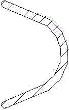
[0027] The first step: first bend the steel strip horizontally into an arc-shaped steel strip;

[0028] The second step: spirally wind the arc-shaped steel strip along the longitudinal direction into multiple conical tubes;

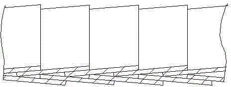
[0029] Step 3: Lap each adjacent two conical cylinders among the plurality of conical cylinders to form a long cylinder;

[0030] Step 4: Pull out a single piece of steel strip from the head end and tail end of the long cylinder for butt welding to form an annular cylinder;

[0031] Step 5: After recovering the two single-piece steel strips welded into conical cylinders, they are then wound back into the respective adjacent conical cylinders;

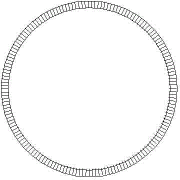
[0032] Step 6: Stamp the ring-shaped barrel obtained in Step 5 to meet the requirements of the drawing, see Figure 1~Figure 3 shown.

Embodiment 2

[0034] In the method for processing metal energy storage springs described in Example 1, in the second step, the inclination angle of each of the tapered cylinders is α=2.8624°.

Embodiment 3

[0036] In the second step of the metal energy storage spring processing method described in Example 1, the circumference of the helix at the small end of the tapered cylinder is 2294.809mm.


PUM

PropertyMeasurementUnit
angleaaaaaaaaaa
perimeteraaaaaaaaaa
perimeteraaaaaaaaaa

Abstract

The invention relates to a metal energy storage spring machining method. The metal energy storage spring machining method includes the following steps that S1, firstly, a steel belt is horizontally bent to be a circular-arc steel belt; S2, the circular-arc steel belt is spirally wound in the longitudinal direction to form a plurality of conical cylinders; S3, every two adjacent conical cylinders in the conical cylinders are connected in a lap joint mode to form a long cylinder; S4, single-piece steel belts are pulled out of the head end of the long cylinder and the tail end of the long cylinder respectively and subjected to butt welding to form an annular cylinder; S5, the two single-piece steel belts generated after butt welding is conducted are wound back into the adjacent conical cylinders respectively after restoring to the conical cylinders. S6, punch forming is conducted on the annular cylinder obtained in S5, and thus the annular cylinder can meet the drawing requirement. The method is used for machining metal energy storage springs.

Description

technical field [0001] The invention relates to a processing method for a metal energy storage spring. Background technique [0002] The V-shaped spring is used in the U-shaped PTFE shell to provide uniform circumferential pressure to achieve the sealing effect. Due to the special structure of the product: it is lap-wound with steel strips and finally needs to be wound into a ring. There is no domestic enterprise that can process such products that meet the design requirements; according to conventional processing methods, after welding, the steel strip cannot be restored to the same shape as other positions, and cannot meet the requirements of the design drawings, resulting in easy failure during use . Contents of the invention [0003] The purpose of the present invention is to provide a new processing method, which greatly improves the yield and durability of metal energy storage spring processing of steel strip winding spring products. [0004] Above-mentioned purpos...

Claims


Application Information

Patent Timeline
Patent Type & Authority Applications(China)
IPC IPC(8): B23P15/00
CPCB23P15/00F16F1/025
Inventor 贾峰孙焕玉朱英男刘金桂
Owner HARBIN DONGAN IND DEV
Why Eureka
Try Eureka