
Electro-pneumatic braking unit controlled by microcomputer for locomotive braking system

An electro-pneumatic braking and braking system technology, applied in the direction of braking transmission, brakes, braking components, etc., can solve the problems that affect the reliability of train braking, train driving safety, braking system paralysis, and failure to work normally. , to facilitate upgrade and maintenance, reduce failure rate, improve reliability and safety

Active Publication Date: 2016-11-30
CRRC QINGDAO SIFANG ROLLING STOCK RES INST +1
View PDF7 Cites 2 Cited by
  • Summary
  • Abstract
  • Description
  • Claims
  • Application Information

AI Technical Summary

Problems solved by technology

Chinese Patent No. CN101323310 discloses a brake control unit for locomotive electro-pneumatic brakes, which accurately collects the pre-control pressure values ​​of the balance air cylinder and brake cylinder through sensors, and uses a microcomputer control system to perform closed-loop control on the balance air cylinder and brake cylinder , and then precisely control the train pipe and brake cylinder. This centralized control method can realize the precise control of the locomotive brake control system to a certain extent. However, since each module of the system cannot independently respond to the control instructions of the brake controller, the entire train system Once there is a problem with the central control unit of the system, the braking system will enter a paralyzed mode, and the train control module, distribution valve control module and individual braking control module of the train cannot work normally, seriously affecting the reliability of the train braking and train safety

Method used


Image

  • Electro-pneumatic braking unit controlled by microcomputer for locomotive braking system
  • Electro-pneumatic braking unit controlled by microcomputer for locomotive braking system
  • Electro-pneumatic braking unit controlled by microcomputer for locomotive braking system

Examples


Embodiment 1

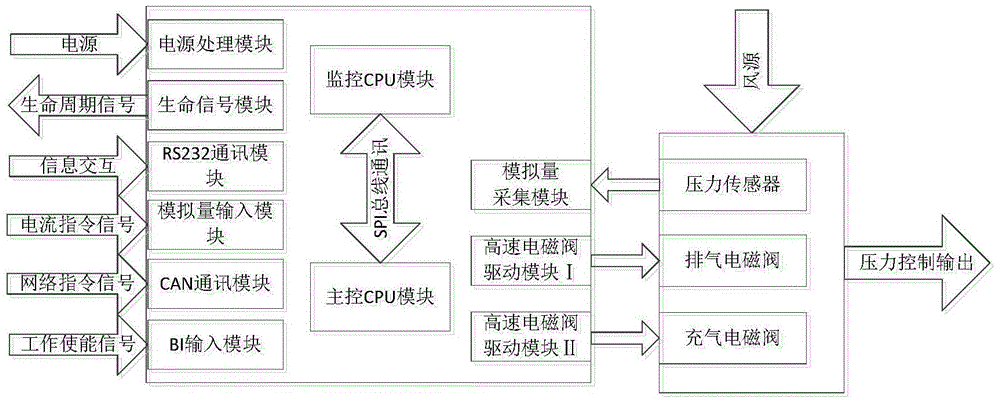
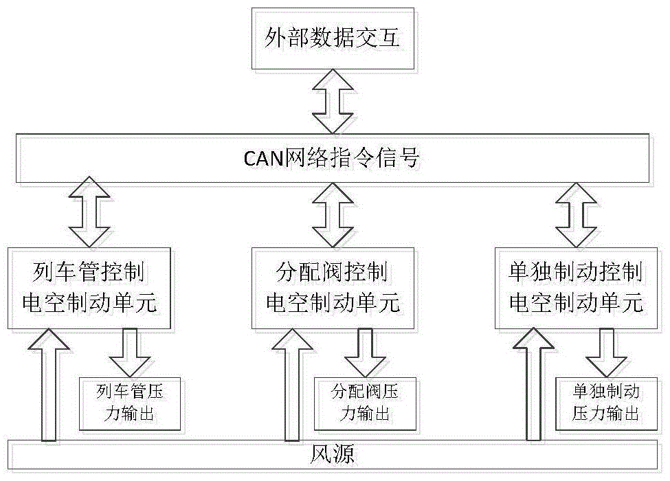
[0037] Such as figure 1 As shown, the present invention discloses a microcomputer-controlled electropneumatic braking unit for locomotive braking systems, which can receive electrical command signals from external systems and complete output control of specified pressures. The electropneumatic braking unit can be applied to trains at the same time Tube control electropneumatic brake unit, distribution valve control electropneumatic brake unit and individual brake control electropneumatic brake unit, the above electropneumatic brake units can independently respond to the control instructions of the brake controller, , Distribution valve and individual brake pressure are controlled.

[0038] The electropneumatic brake unit mainly includes two parts: the air circuit part and the electric part.

[0039] The air circuit part is mainly composed of inflation solenoid valve, exhaust solenoid valve and pressure sensor. Among them, the inflation solenoid valve and the exhaust solenoid...


PUM


Abstract

The invention relates to a microcontroller control electro-pneumatic brake unit for locomotive brake systems and aims to achieve conversion of electrical signals of a locomotive brake system and an air brake pressure signal. The microcontroller control electro-pneumatic brake unit comprises an air circuit portion and an electrical portion; the air circuit portion mainly comprises an intake electromagnetic valve, an exhaust electromagnetic valve and a pressure sensor. The electrical portion mainly comprises a life signal module, an RS232 communication module, an analog input module, a CAN (controlled area network) communication module, a BI (batch input) module, a master control CPU (central processing unit) module, a monitoring CPU module, a high-speed electromagnetic valve drive module, an analog acquiring module and a power processing module powering the modules above. The electro-pneumatic brake units in a brake control system can automatically control train tubes, distributor valves and independent brake pressures, separately, automatically in response to control commands of the electro-pneumatic brake units, the stability of the brake control system is improved, and fault rate is decreased.

Description

technical field [0001] The invention relates to the field of railway locomotive braking, in particular to a microcomputer-controlled electro-pneumatic braking unit for a locomotive braking system. Background technique [0002] With the intelligentization and network development trend of the locomotive braking system, the original pure air control method in the locomotive braking system is gradually eliminated, and the locomotive braking system controlled by a microcomputer has become the mainstream of existing products. The braking control of the train by the locomotive braking system is mainly realized through the following three important modules, which are the train control module, the distribution valve control module and the individual brake control module. The command signal is converted into an air pressure signal, and the train pipe pressure, distribution valve pressure and individual brake pressure are respectively controlled. [0003] Among them, the train pipe co...

Claims


Application Information

Patent Timeline
Patent Type & Authority Patents(China)
IPC IPC(8): B61H11/06B60T8/34B60T13/66
CPCB60T8/34B60T13/665B61H11/06
Inventor 任向杰王令军孙彬吕枭王帅帅石喆文
Owner CRRC QINGDAO SIFANG ROLLING STOCK RES INST
Learn More