
Smoke recycling rubbish incineration boiler

A technology of flue gas recirculation and waste incineration, applied in incinerators, combustion methods, combustion types, etc., to achieve the effects of improving thermal efficiency, reducing dust volume, and extending operating time

Active Publication Date: 2015-05-20
潘韬任
View PDF5 Cites 4 Cited by
  • Summary
  • Abstract
  • Description
  • Claims
  • Application Information

AI Technical Summary

Problems solved by technology

[0004] The object of the present invention is to provide a flue gas recirculation waste incineration boiler to solve the shortcomings of existing reciprocating mechanical grate waste incineration boilers

Method used


Image

  • Smoke recycling rubbish incineration boiler
  • Smoke recycling rubbish incineration boiler
  • Smoke recycling rubbish incineration boiler

Examples


Embodiment

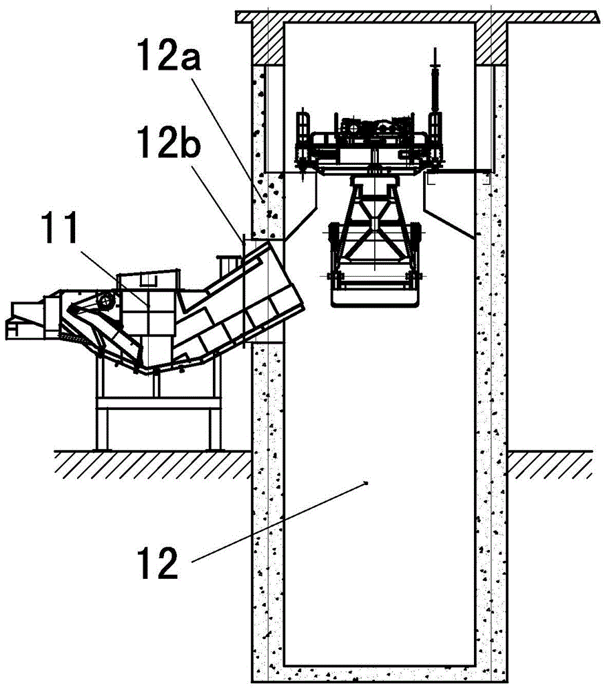
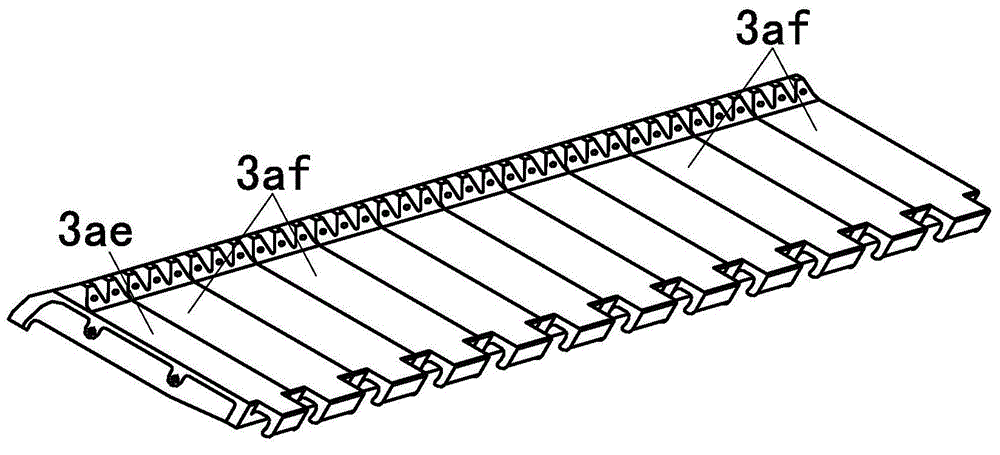
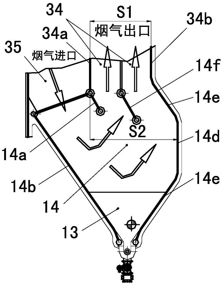
[0035] The schematic diagram of the structure of the flue gas recirculation waste incineration boiler in this embodiment is as follows Figure 1-15 As shown, the flue gas recirculation waste incineration boiler includes a boiler steel frame 26 and a furnace 2 installed on the boiler steel frame; a grate mounting bracket 39 is arranged below the furnace 2, and a reciprocating mechanical grate is installed on the grate mounting bracket 39 3; After the flue gas outlet at the top of the furnace 2, the first shaft flue 1, the second shaft flue 35, the third shaft flue 34, the horizontal flue 30, the first vertical tail flue 24 and the first shaft flue 24 connected in sequence are arranged. The second vertical tail flue 19; the second vertical shaft flue 35 and the third vertical shaft flue 34 below are provided with a dust-reducing flue gas chamber 14, and the inlet end and the outlet end of the dust-reducing flue gas chamber 14 are connected with the second vertical shaft flue 35 r...


PUM


Abstract

The invention relates to a smoke recycling rubbish incineration boiler. The smoke recycling rubbish incineration boiler comprises a boiler steel frame and a furnace arranged on the boiler steel frame. A grate mounting frame is arranged under the furnace, and a reciprocating machinery grate is arranged on the grate mounting frame. The rear part, of a smoke outlet, on the top of the furnace is provided with a first shaft flue, a second shaft flue, a third shaft flue, a horizontal flue, a first vertical rear flue and a second vertical rear flue which are connected in order. A smoke outlet A formed in the upper portion of the second vertical rear flue is connected with the smoke recycling nozzles arranged on the back wall and the front wall of a furnace exit through a smoke recycling system. A precipitator is arranged between the exit of the first vertical rear flue and the entrance of the second vertical rear flue. The smoke recycling rubbish incineration boiler has the advantages that the drying sludge can be burned at the time of rubbish incineration disposal, the heat loss due to exhaust gas of the boiler is decreased by more than 15%, the heat efficiency is increased by more than 2.2%, the dust capacity of the smoke in the exit of the boiler is decreased by more than 90%, the continuous running time is long, and effects of high efficiency, energy conservation and emission reduction can be achieved.

Description

technical field [0001] The invention relates to a waste incineration boiler for flue gas recirculation, which belongs to the technical field of waste incineration power generation. Background technique [0002] At present, waste incineration boilers used for waste incineration power generation mainly include three types: rotary kiln waste incineration boilers, fluidized bed waste incineration boilers and reciprocating mechanical grate waste incineration boilers. Among them, the reciprocating mechanical grate waste incineration boiler technology is currently the most suitable technology for incinerating waste and using the heat energy generated by waste incineration to produce steam for power generation, so it has been widely used at home and abroad. The technical characteristics of the reciprocating mechanical grate waste incineration boiler are as follows: 1. Oil or natural gas can be used as auxiliary fuel without burning coal; 2.) Garbage can be directly incinerated witho...

Claims


Application Information

Patent Timeline
Patent Type & Authority Applications(China)
IPC IPC(8): F23G5/00F23G5/44
CPCF23G5/00F23G5/44F23G7/001F23G2202/106F23G2209/12F23G2900/00001
Inventor 潘老省
Owner 潘韬任
Learn More