Solid fuel furnace with thermoelectric power generation device

A solid fuel, temperature difference power generation technology, applied in the direction of solid heating fuel, circuit devices, battery circuit devices, etc., can solve the problems of difficulty in providing stable power supply, complex structure of power generation devices, inconvenient use and carrying, and achieve compactness, lightness, The effect of simple structure and simple operation

Inactive Publication Date: 2015-05-20
HUNAN XUNDA JI TUAN YOU XIAN GONG SI
View PDF5 Cites 11 Cited by
  • Summary
  • Abstract
  • Description
  • Claims
  • Application Information

AI Technical Summary

Problems solved by technology

[0002] With the development of agriculture and forestry, there will be more and more biomass resources. In recent years, biomass furnaces have developed greatly. Naturally induced air or forced air are generally used, and fans are used to force air. The operation is easier and the combustion effect is better, but a power supply is necessary, and it is difficult to provide a stable power supply for relatively remote areas and outdoor operations
[0003] Some stove products have their own power generation device, but there are many problems. First, the structure of the power generation device is relatively complicated, and the volume is relatively large, which is inconvenient to use and carry. Secondly, because it is not fully compatible with the stove, the fuel combustion is not good Sufficient, poor combustion effect or unstable power supply, poor continuity

Method used


Image

  • Solid fuel furnace with thermoelectric power generation device
  • Solid fuel furnace with thermoelectric power generation device
  • Solid fuel furnace with thermoelectric power generation device

Examples


Embodiment Construction

[0021] The present invention will be described in further detail below in conjunction with the accompanying drawings.

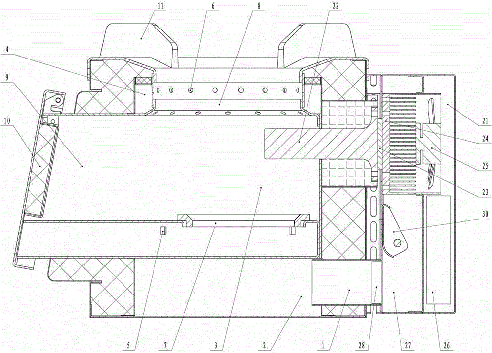
[0022] Such as figure 1 As shown, a solid fuel furnace with a thermoelectric power generation device includes a solid fuel furnace and a thermoelectric power generation device. Such as figure 1 , Figure 4 As shown, there is an air duct 1 for providing combustion-supporting air at the bottom of the solid fuel furnace. The air duct 1 is connected to the ventilation chamber 2. The air chamber 2 is a square structure. The furnace 3 of the solid fuel furnace is a cylindrical structure located in the wind chamber. Inside the chamber 2, the furnace wall of the furnace 3 is connected to the four vertical sides of the air chamber 2 to form four independent air ducts 4, and the air duct 4 is provided with a primary air hole 5 and a secondary air hole 6 corresponding to the furnace connected to the bottom of the furnace. The bridge 7 and the fire outlet 8 on the upp...


PUM


Abstract

The invention relates to a solid fuel furnace with a thermoelectric power generation device. The solid fuel furnace comprises a solid fuel furnace and a thermoelectric power generation device; the lower end of a blower box of the thermoelectric power generation device is provided with an exhaust room, and the exhaust room is provided with an air pipe for connecting an exhaust hole with the solid fuel furnace; the air exhaust room is further provided with an air volume balance hole, and an air flap and an adjusting handle are installed in the exhaust room; the air flap is adjusted to close the air exhaust hole or the air volume balance hole, and make that the total air volume is unchanged while the air exhaust volumes of the air exhaust hole and the air volume balance hole are in an inversely proportional relationship. The solid fuel furnace can externally provide stable and enough power source without externally connecting the power source; through reasonable distribution of primary and secondary air, the fuel is fully burned; the solid fuel furnace is featured by simple operation, high burning heat efficiency, and few smoke gas emission; the fuel adaption is wide, and it is especially applicable to various fuel wood and other biomass solid fuels; besides, the solid fuel furnace is simple, small and light in structure, and applicable to indoor cooking and outdoor cooking.

Description

technical field [0001] The invention relates to a solid fuel stove, in particular to a solid fuel stove with a thermoelectric power generation device suitable for domestic and outdoor use. Background technique [0002] With the development of agriculture and forestry, there will be more and more biomass resources. In recent years, biomass furnaces have developed greatly. Naturally induced air or forced air are generally used, and fans are used to force air. The operation is easier and the combustion effect is better, but a power supply is necessary, and it is more difficult to provide a stable power supply for relatively remote areas and outdoor operations. [0003] Some stove products have their own power generation device, but there are many problems. First, the structure of the power generation device is relatively complicated, and the volume is relatively large, which is inconvenient to use and carry. Secondly, because it is not fully compatible with the stove, the fuel ...

Claims


Application Information

Patent Timeline
Patent Type & Authority Applications(China)
IPC IPC(8): F24B1/18F24B1/191H02J7/32
CPCY02B40/00Y02P80/20
Inventor 伍斌强刘炎俊周科文郭聪颖伍曼娇伍奕
Owner HUNAN XUNDA JI TUAN YOU XIAN GONG SI
Why Eureka
Try Eureka