
Vacuum induction furnace

A vacuum induction furnace and vacuum system technology, applied in furnaces, crucible furnaces, furnace types, etc., can solve the problems of inability to effectively reduce the pressure in the furnace, difficult to grasp the actual temperature, and eliminate dangers, saving materials and high measurement accuracy. , the effect of thin thickness

Inactive Publication Date: 2015-05-20
DANYANG ZHISHENG ALLOY
View PDF6 Cites 0 Cited by
  • Summary
  • Abstract
  • Description
  • Claims
  • Application Information

AI Technical Summary

Problems solved by technology

[0002] Vacuum induction furnace is mainly used for smelting treatment of metal materials (such as stainless steel, nickel-based alloy, copper, alloy steel, nickel-cobalt alloy, rare earth neodymium iron stiltium, etc.) , can also carry out vacuum refining treatment and precision casting of alloy steel. The application number is CN 201220061216.5, which discloses a vertical metal distillation vacuum induction furnace. In the same furnace body, the induction coil is wound with double copper tubes, and at the same time it is cooled by itself, and the condensation cover attached to it is cooled, so that the recovered liquid distillation metal flows smoothly into the liquid storage tank to prevent the occurrence of secondary distillation; the induction coil and the vacuum furnace The body is connected to reduce the pressure difference; the liquid storage tank of the furnace body can be separated from the furnace body, which is convenient for cleaning and maintenance of the liquid storage tank. However, when the air pressure in the furnace is too high, the equipment cannot effectively reduce the air pressure in the furnace and eliminate the danger. And the actual temperature in the furnace is not easy to grasp

Method used


Image

  • Vacuum induction furnace
  • Vacuum induction furnace

Examples


Embodiment Construction

[0013] In order to make the technical means, creative features, goals and effects achieved by the present invention easy to understand, the present invention will be further described below in conjunction with specific embodiments.

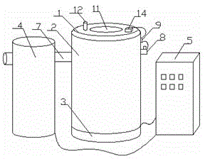
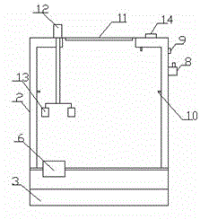
[0014] Such as figure 1 and figure 2 As shown, a vacuum induction furnace includes a furnace cover 1, a furnace body 2, a furnace bottom 3, a vacuum system 4, and an intermediate frequency power supply control system 5. The furnace cover 1 is arranged on the top of the furnace body 2, and the inside of the furnace body 2 is A crucible 6 is provided, the vacuum system 4 is connected to the furnace body 2 through a vacuum pipeline 7, the intermediate frequency power supply control system 5 is electrically connected to the furnace body 2 and the vacuum system 4, and the furnace body 2 is provided with an air release valve 8. A control switch 9 is connected to the deflation valve 8, four infrared thermometers 10 are arranged inside the furnace body...


PUM

PropertyMeasurementUnit
diameteraaaaaaaaaa
thicknessaaaaaaaaaa

Abstract

The invention discloses a vacuum induction furnace, and relates to the field of machining and manufacturing of iron chromium aluminum alloy. The vacuum induction furnace comprises a furnace cover, a furnace body, a furnace bottom, a vacuum system and a medium-frequency power supply control system. The furnace cover is arranged on the top of the furnace body, and a crucible is arranged inside the furnace body; the vacuum system is connected with the furnace body through a vacuum pipeline; the medium-frequency power supply control system is electrically connected with the furnace body and the vacuum system; a deflation valve is arranged on the furnace body and is connected with a control switch; four infrared thermometers are arranged inside the furnace body, and the diameter of the vacuum pipeline ranges from 8 cm to 10 cm; and under the condition that air pressure in the furnace is too large suddenly, the deflation valve is opened, external air enters the furnace, and the air pressure in the furnace is reduced. Actual temperature inside the furnace body can be effectively measured, the measuring precision is high, and a worker can grasp the temperature inside the furnace body in real time.

Description

technical field [0001] The invention relates to the field of processing and manufacturing iron-chromium-aluminum alloys, in particular to a vacuum induction furnace. Background technique [0002] Vacuum induction furnace is mainly used for smelting treatment of metal materials (such as stainless steel, nickel-based alloy, copper, alloy steel, nickel-cobalt alloy, rare earth neodymium iron stiltium, etc.) , can also carry out vacuum refining treatment and precision casting of alloy steel. The application number is CN 201220061216.5, which discloses a vertical vacuum induction furnace for metal distillation. In the same furnace body, the induction coil is wound with double copper tubes, and at the same time it is cooled by itself, and the condensation cover attached to it is cooled, so that the recovered liquid distillation metal flows smoothly into the liquid storage tank to prevent the occurrence of secondary distillation; the induction coil and the vacuum furnace The body ...

Claims


Application Information

Patent Timeline
Patent Type & Authority Applications(China)
IPC IPC(8): F27B14/04F27B14/20F27B14/12
Inventor 王良玉张坚刘浩方
Owner DANYANG ZHISHENG ALLOY
Learn More