Hinge machining host and machining method

A main machine and hinge technology, applied in metal processing machinery parts, metal processing, metal processing equipment, etc., can solve the problems of high processing cost, difficult coordination of processing rhythm, and low processing efficiency

Active Publication Date: 2015-05-27
济南天辰智能装备股份有限公司
View PDF6 Cites 22 Cited by
  • Summary
  • Abstract
  • Description
  • Claims
  • Application Information

AI Technical Summary

Problems solved by technology

[0003] In the existing technology, the processing of each station is often realized by a single machine operation, such as cutting the specified length through a single-head cutting saw, cutting the hinge profile into a specified length of material section; transferring the profile of each material section to the punch station On the top, complete the stamping of the matching groove and the mounting hole; transfer the stamped profile to the multi-head drilling machine station to complete the countersinking

Method used


Image

  • Hinge machining host and machining method
  • Hinge machining host and machining method
  • Hinge machining host and machining method

Examples


Embodiment 1

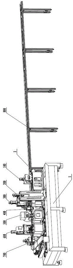
[0087] Such as figure 1 As shown, a hinge processing main engine includes a bed 1, a control system and a hydraulic system. The bed 1 is sequentially installed with an automatic feeding device 100, a sawing device, a sawing and pressing device 400, a stamping Device 500 , drilling device 600 and cutting device 700 .

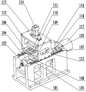
[0088] Such as figure 2 As shown, the automatic feeding device 100 includes a feeding base 101, a right screw seat 102 and a left screw seat 103 fixed on the feeding base 101, and is rotatably connected between the right screw seat 102 and the left screw seat 103 The leading screw 104, the screw nut 105 engaged with the leading screw 104, the screw nut 105 is fixed on the screw nut seat 106;

[0089] Two guide rails-107 are also fixed on the described feeding base 101, and 2 slide blocks-108 are slidably connected on each guide rail-107, and the bottom of the feed slide plate 109 is fixedly connected on 4 slide blocks-108, and the feed slide plate The top of ...

Embodiment 2

[0131] A method for processing a hinge using the hinge processing host, comprising the following steps:

[0132] a) The control system starts the hydraulic system, starts the sawing motor 205, the drilling motor 606 and the cutting motor 705;

[0133] b) The control system controls the feeding and pressing cylinder 114 in the feeding device 100 to press the two profiles 2 symmetrically placed in the feeding backing plate 110, and the servo motor 117 drives the screw 104 to rotate and drives the feeding slide 109 to move for feeding ;

[0134] c) The control system controls the vertical compression cylinder 405 for sawing, the horizontal compression cylinder 407 before sawing, the horizontal compression cylinder 409 after sawing, the compression cylinder 624 before drilling, the compression cylinder 627 after drilling, and the vertical compression cylinder for cutting. The straight compression cylinder 721, the compression cylinder 723 before cutting and the compression cylind...


PUM


Abstract

The invention discloses a hinge machining host. The hinge machining host comprises a lathe bed, a control system and a hydraulic system; an automatic feeding device, a sawing device, a sawing compacting device, a punching device, a drilling device and a cutting device are arranged sequentially on the lathe bed along the feeding direction; the sawing device further comprises a front sawing device and a rear sawing device, the structure of the front sawing device is the same as the structure of the rear sawing device, the front and back sawing devices are arranged symmetrically front and back; a supporting device is arranged on the right side of the automatic feeding device; a service motor drives the feeding, the transmission precision is high; each station machines at the same time, the progresses are the same, and the machining efficiency is high. The invention further discloses a method for machining the hinge by the device disclosed by the invention; the method comprises the following steps: the feeding device compacts profiles and feeds; each station compacts the profiles; the sawing, punching, drilling and cutting devices machine the profiles at the same time; each station returns; the feeding device releases the profiles; the feeding device returns back to the initial position; the feeding device compacts the profiles again; each station looses the profiles; the feeding device feeds again; and then the next process is performed.

Description

technical field [0001] The invention relates to a metal hinge processing host and a processing method thereof, belonging to the technical field of hinge profile processing equipment. Background technique [0002] In the field of metal hinge processing, it is necessary to cut the 6-meter-long hinge profile into material sections of specified length, and then process mounting holes, punch out matching grooves and drill countersunk holes on each material section. [0003] In the existing technology, the processing of each station is often realized by a single machine operation, such as cutting the specified length through a single-head cutting saw, cutting the hinge profile into a specified length of material; transferring the profile of each material section to the punching station On the top, complete the stamping of the matching groove and the mounting hole; transfer the stamped profile to the multi-head drilling machine station, and complete the countersinking of the mounti...

Claims


Application Information

Patent Timeline
IPC IPC(8): B23P23/04B23D47/02B23D47/04B21D22/02B23B41/00B23Q3/08B23B47/22B23B47/06B23Q7/00B23P15/00
CPCB21D22/02B23B41/00B23D47/02B23P15/00B23P23/04B23Q3/082B23Q5/10B23Q5/26B23Q7/00
Inventor 张修福郭宁杨向东
Owner 济南天辰智能装备股份有限公司
Why Eureka
Try Eureka