Eureka AIR delivers breakthrough ideas for toughest innovation challenges, trusted by R&D personnel around the world.

Production method of composite ceramic core for single crystal hollow blade of complex structure

A hollow blade, complex structure technology, applied in the field of superalloys

Active Publication Date: 2015-05-27
INST OF METAL RESEARCH - CHINESE ACAD OF SCI
View PDF9 Cites 2 Cited by
  • Summary
  • Abstract
  • Description
  • Claims
  • Application Information

AI Technical Summary

Problems solved by technology

Single-crystal alloy blades can be used at higher temperatures because they remove the influence of grain boundaries, usually 30°C higher than oriented alloy blades, and nearly 100°C higher than polycrystalline blades, but this still cannot fully meet the requirements of the modern aviation industry

Method used


Image

  • Production method of composite ceramic core for single crystal hollow blade of complex structure
  • Production method of composite ceramic core for single crystal hollow blade of complex structure
  • Production method of composite ceramic core for single crystal hollow blade of complex structure

Examples


Embodiment 1

[0021] Preparation of locally strengthened composite ceramic core:

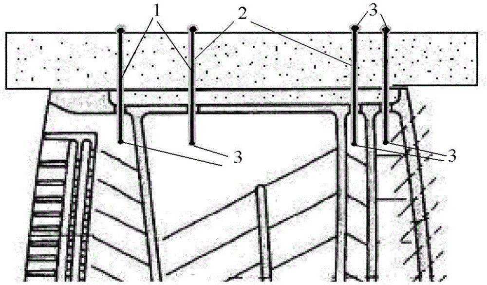
[0022] The molybdenum wire with a diameter of 0.08 mm is cut into a molybdenum wire segment with a length of 5 mm, and the two ends of the molybdenum wire segment are arc-welded to make the two ends of the molybdenum wire into a spherical shape with a diameter of 0.2 mm to form a molybdenum wire fixing mechanism. Then adopt CVD to deposit silicon dioxide on the surface of the molybdenum wire section, the thickness of the silicon dioxide thin layer is 10 microns; then the molybdenum wire section is placed in the fixed groove in the ceramic core mold to fix (see figure 2 ), the ceramic core blank was prepared by injection molding, the ceramic slurry was a silica-based material, the molding pressure was 0.8MPa, the injection time was 20 seconds, and the pressure holding time was 20 seconds; the sintering process of the composite core was: The dewaxing stage of the ceramic core is sintered with low temperature a...

Embodiment 2

[0026] The high-purity molybdenum wire with a diameter of 0.1 mm is cut into molybdenum wire segments with a length of 10 mm. The two ends of the molybdenum wire segment are welded by argon arc to make the two ends of the molybdenum wire into a spherical shape with a diameter of 0.25 mm to form a fixing mechanism. Then PVD is used to deposit silicon dioxide on the surface of the molybdenum wire segment, and the thickness of the silicon dioxide thin layer is 20 microns; it is then fixed in a ceramic core mold, and the ceramic core blank is prepared by injection molding, and the ceramic slurry is Alumina-based materials, the molding pressure is 0.5MPa, the injection time is 30 seconds, and the pressure holding time is 30 seconds; the sintering process of the composite core is: the ceramic core is sintered at a low temperature and slowly raised during the dewaxing stage, and the heating rate is controlled at 0.8°C / min, temperature 600°C, holding time 2 hours; the final sintering ...

Embodiment 3

[0030]The high-purity molybdenum wire with a diameter of 0.16 mm is cut into molybdenum wire segments with a length of 10 mm. The two ends of the molybdenum wire segment are welded by argon arc to make the two ends of the molybdenum wire into a spherical shape with a diameter of 0.4 mm to form a fixing mechanism. Then use the sol-gel method to deposit alumina on the surface of the molybdenum wire segment, the thickness of the aluminum oxide thin layer is 100 microns; then place the molybdenum wire segment in the ceramic core mold and fix it, and prepare the ceramic core element by injection molding The blank, the ceramic slurry is silica-based, the molding pressure is 0.8MPa, the injection time is 120 seconds, and the pressure holding time is 120 seconds; the sintering process of the composite core is: the ceramic core dewaxing stage is sintered at low temperature and slowly The heating rate is controlled at 1°C / min, the temperature is 600°C, and the holding time is 2 hours; th...


PUM

PropertyMeasurementUnit
Diameteraaaaaaaaaa
Lengthaaaaaaaaaa
Thicknessaaaaaaaaaa

Abstract

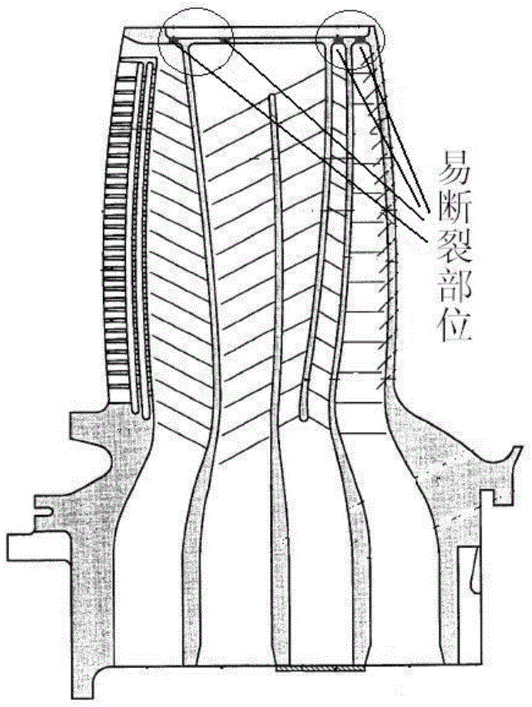
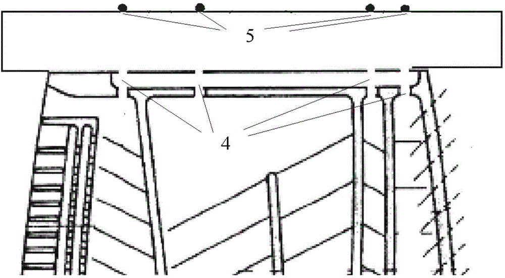
The invention provides a production method of a composite ceramic core for a single crystal hollow blade of a complex structure. The specific production process of the production method includes that a molybdenum wire is cut into a segment, the treatment is performed on two ends of the molybdenum wire segment to form a ball head at each end of the molybdenum wire, and the shape size of each ball head is larger than the diameter of the molybdenum wire; a ceramic layer is deposited on the surface of the integral molybdenum wire segment and the molybdenum wire segment after the ceramic deposition is placed into a position of a ceramic core die to be fixed, wherein the ceramic core is easy to fracture at the position; a ceramic core biscuit is produced by an injection forming method and the ceramic core is obtained after being sintered. According to the production method of the composite ceramic core for the single crystal hollow blade of the complex structure, thin layer of silicon dioxide or aluminum oxide wraps the surface of the molybdenum wire to enhance the local strength of the ceramic core, the molybdenum wire position in the core is fixed through the ball head which is arranged at each end of the molybdenum wire, and accordingly the fracture of the fine position of the ceramic core is avoided, the qualification rate of the single crystal blade is improved, and the requirement for the high qualification rate of the production of the single crystal turbine blade of the complex inner chamber structure is met.

Description

technical field [0001] The invention belongs to the technical field of superalloys, and in particular relates to a preparation method of a composite ceramic core for single-crystal hollow blades with complex structures. Background technique [0002] The most critical hot-end part of an aero-engine is the turbine blade. In order to improve thermal efficiency, the temperature of the air in front of the turbine blade is getting higher and higher. Single crystal alloy blades remove the influence of grain boundaries and thus can be used at higher temperatures, usually 30°C higher than oriented alloy blades and nearly 100°C higher than polycrystalline blades, but this cannot fully meet the requirements of the modern aviation industry. Therefore, air cooling technology is used in all gas turbine blades today. The air cooling effect is closely related to the air cooling structure of the blade. In order to pursue a higher air cooling effect, the hollow structure of the blade is beco...

Claims


Application Information

Patent Timeline
IPC IPC(8): B28B23/02B28B1/24
CPCB28B1/32B28B23/02B28B23/024
Inventor 姜卫国李凯文王迪张健楼琅洪王莉刘畅
Owner INST OF METAL RESEARCH - CHINESE ACAD OF SCI
Why Eureka
Eureka Blog
Learn More